
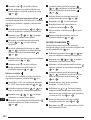
TLM165S, TLM165SI, TLM330S
User Manual
Please read these instructions before operating the product.
www.2helpU.com
DOC100270398
GB
NL
GR
I
FIN
HU
BG
LV
D
DK
CZ
ES
NO
SK
RO
LT
F
SE
RU
PT
PL
SI
EE
TR
HR

C
D
AAA
AAA
AAA
AAA
AAA
50.0°
0.7000 m
0.0000 m
0.0000 m
0.0000 m
50.0°
0.7760m
1.3470 m
0.4070 m
max
min
B
2
GB
A
2
1
3

3
GB
F
4
3
1
2
7
5
6
50.0°
0.0000 m
0.0000 m
0.0000 m
0.0000 m
8
9
E
2
1
3
4
=
=
=
=

4
GB
G
ft/m
TLM165S
TLM165SI
TLM330S
H
50.0°
0.0000 m
0.0000 m
0.0000 m
0.0000 m
a
a
1
2
3

5
GB
I
K
50.0°
0.3000 m
0.7000 m
+
1.0000m
+
-
/
50.0°
0.1500 m
1.0000 m
-
0.8500m
+
-
/
L
J
50.0°
0.2400m
0.4000 m
0.6000 m
2
+
2
50.0°
0.4500 m
0.2400 m
0.2100 m
+
-
/
2
2
+/-

6
GB
M
N
50.0°
1.0100m
2.7390 m
2.1000 m
?
O
?
P
50.0°
0.2100 m
0.5000 m
0.7000 m
0.6000 m
3
+
2.6520 m
0.0420 m
3
3
3
50.0°
2.6940 m
+
-
/
50.0°
0.0210 m
0.300 m
0.700 m
+/-

7
GB
?
Q R
24.3°
4.8270m
0.0320 m
24.3°
?
50.0°
0.6000 m
3.0000 m
1.0000 m
2.0000 m

8
GB
30.2°
9.8270 m
6.9320 m
30.2°
S
T
86.5°
15.0°
50.0°

9
GB
U
12”
12”
12”
12”
50.0°
0.00 in
12.00 in
12.00 in
a
a
12” 12”
50.0°
0.00 in
12.00 in
12.00 in
a
a
12”
0.000 in
0.00 in
12.0 in
50.0°
a
a
12”

10
GB
W
180°
90°
180°
?
86.5°
86.5°
V

11
GB
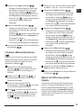
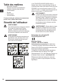
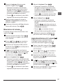
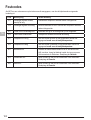
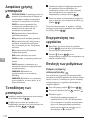
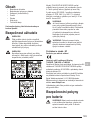
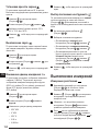
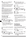
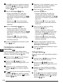
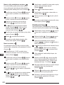
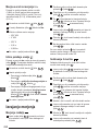
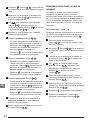
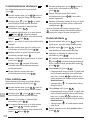
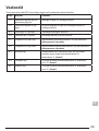
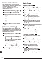
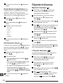
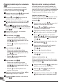
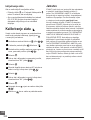
Contents
• User Safety
• Battery Safety
• Setup (Load Batteries)
• Operation
• Warranty
• Error Codes
• Specications
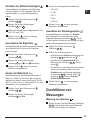
Retain all sections of this manual for future
reference.
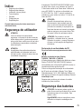
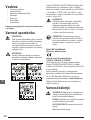
User Safety
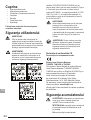
WARNING:
Carefully read the Safety Instructions and
Product Manual before using this product.
The person responsible for the product
must ensure that all users understand and
adhere to these instructions.
WARNING:
The following label information is placed
on your laser tool to inform you of the laser
class for your convenience and safety.
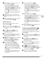
The TLM165S/TLM165SI/TLM330S tool
emits a visible laser beam, as shown in
Figure A. The laser beam emitted is Laser
Class 2 per IEC 60825-1 and complies with
21 CFR 1040.10 and 1040.11 except for
deviations pursuant to Laser Notice No. 50,
dated June 24, 2007.
WARNING:
While the laser tool is in operation, be
careful not to expose your eyes to the
emitting laser beam (red light source).
Exposure to a laser beam for an extended
time period may be hazardous to your eyes.
Do not look into the beam with optical aids.
WARNING: To reduce the risk of injury,
user must read the Product User manual,
Laser Safety manual, and Battery Safety
information.
EC-Declaration of Conformity
Radio Equipment Directive
Stanley Laser Distance Measurer
TLM165S, TLM165SI and TLM330S
Stanley hereby declares that the Stanley Laser
Distance Measurer TLM165S/TLM165SI/TLM330S is
in compliance with the Directive 2014/53/EU and to all
applicable EU directive requirements.
The full text of the EU Declaration of Conformity
can be requested at Stanley Tools, Egide
Walschaertsstraat 14-16, 2800 Mechelen, Belgium
or is available at the following internet address:
www.2helpU.com.
Search by the Product and Type Number indicated on
the nameplate.
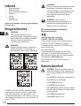
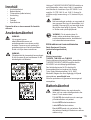
Battery Safety
WARNING: Batteries can explode or leak
and cause serious injury or re. To reduce
the risk:
ALWAYS follow all instructions and
warnings on the battery label and package.
DO NOT short any battery terminals.
DO NOT charge alkaline batteries.
DO NOT mix old and new batteries.
Replace all of them at the same time with
new batteries of the same brand and type.
DO NOT mix battery chemistries.
DO NOT dispose of batteries in re.
ALWAYS keep batteries out of reach of
children.

12
GB
ALWAYS remove batteries if the device will
not be used for several months.
NOTE: Ensure that the recommended
batteries are used.
NOTE: Ensure the batteries are inserted
in the correct manner, with the correct
polarity.
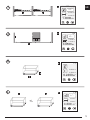
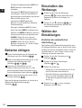
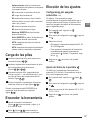
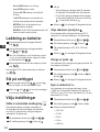
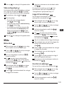
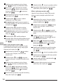
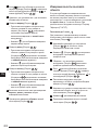
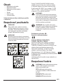
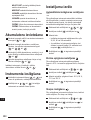
Loading Batteries
1.
Pull up the endpiece on the back of the tool
(Figure
D
1
).
2.
Pull up the battery compartment latch on the back
of the tool (Figure
D
2
and
D
3
).
3.
Insert three AAA batteries, making sure to position
the - and + ends of each battery as noted inside
the battery compartment (Figure
D
4
).
4.
Push the battery door down until it snaps in place
(Figure
D
5
).
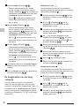
When the tool is ON, the battery level appears on the
screen (Figure
E
1
).
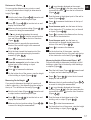
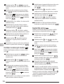
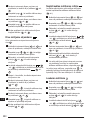
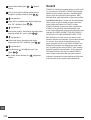
Turning the Tool On
1.
Point the tool's laser (Figure
A
1
) toward a wall
or object, and not toward anyone's eyes.
2.
Click (Figure
A
3
) to turn the tool on and
display the red laser dot.
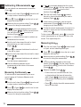
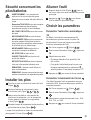
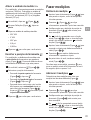
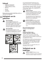
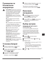
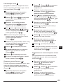
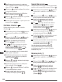
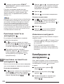
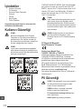
Choosing the Settings
Setting Automatic Turn Off
By default, the tool will automatically turn off 90
seconds after no buttons or options have been
selected. To change when the tool turns off
automatically, follow these steps.
1.
On the touchscreen, click (Figure
E
8
).
2.
On the Settings Menu (Figure
H
), click .
3.
Select the time.
• Choose to turn the tool off after 30 sec, 60 secs,
90 secs, or 300 secs.
• To keep the tool turned on until you manually
turn it off (by pressing and holding
for
10 seconds), click
∞
.
4.
Click to return to the previous screen.
Setting Screen Brightness
By default, the tool's screen will be set at 25%
brightness. To change the brightness level, follow
these steps.
1.
On the touchscreen, click (Figure
E
8
).
2.
On the Settings Menu (Figure
H
), click .
3.
Select the desired brightness level: 25%, 50%,
75%, or 100%.
4.
Click to return to the previous screen.
Turning Off the Sound
By default, the tool will beep each time you take
a measurement. You can turn off the beeps.
1.
On the touchscreen, click (Figure
E
8
).
2.
On the Settings Menu (Figure
H
), click to
display
.
3.
Click to return to the previous screen.
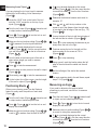
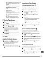
Changing the Unit of Measure
ft/m
By default, the tool will display measurements in
meters (1.8940 m). You can change the unit of
measure to fractional ft (6'02"
9/16), inches (74 9/16 in),
decimal ft (6.21 ft), or decimal inches (3.21 in).
1.
On the touchscreen, click (Figure
E
8
).
2.
On the Settings Menu (Figure
H
), click ft/m.

13
GB
3.
Click the desired unit of measure.
• 0'00" 0/00
• 0" 0/00
• 0'00" ft
• 0.00 in
• 0.0000 m
4.
Click to return to the previous screen.
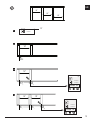
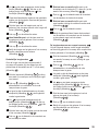
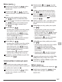
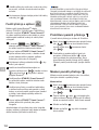
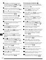
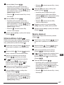
Choosing the Tool Position
By default, distances are measured from the bottom
of the tool to a wall or object (Figure
F
3
). To
measure distances from a different tool location, follow
these steps.
1.
On the touchscreen, select (Figure
C
4
).
2.
Select the tool position.
• To measure from the top of the tool
(Figure
F
1
), click .
• To measure from the tripod connection on the
tool (Figure
F
2
), click .
• To measure from a corner or another hard-to-
reach location with the endpiece flipped open
at the bottom of the tool (Figure
D
1
), click
(Figure
F
4
) to measure from the end of
the endpiece.
3.
Click to return to the previous screen.
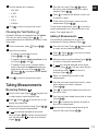
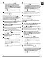
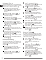
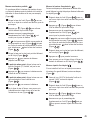
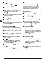
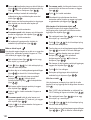
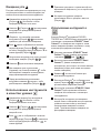
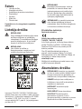
Taking Measurements
Measuring Distance
1.
Point the tool's laser (Figure
A
1
) toward a wall
or object, and not toward anyone's eyes.
2.
Press (Figure
A
3
) to turn the tool on and
display the red laser dot.
3.
Make sure the tool position setting (Figure
E
4
)
is correct for taking the measurement.
4.
If is not already displayed as the current
function (Figure
E
5
), click the current function
icon and then select
from the list of functions
(Figure
G
1
).
5.
Point the tool's laser (Figure
A
1
) toward
the wall or object whose distance you need to
measure (Figure
B
1
).
6.
Press to measure the distance from the tool
to the wall or object.
7
At the bottom of the screen, view the current
measurement (Figure
B
2
).
To take a new measurement, press
to move the
current measurement up to the previous line on the
screen. Then repeat steps 3-6.
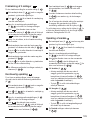
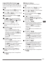
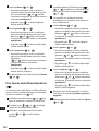
Adding 2 Measurements
You can add two measurements to get a total
measurement of the two distances (Figure
I
).
1.
Point the tool's laser (Figure
A
1
) toward a wall
or object, and not toward anyone's eyes.
2.
Press (Figure
A
3
) to turn the tool on and
display the red laser dot.
3.
Make sure the tool position setting (Figure
E
4
)
is correct for taking the measurement.
4.
If is not already displayed as the current
function (Figure
E
5
), click the current function
icon and then select
from the list of
functions (Figure
G
1
).
5.
Select + to indicate that you want to add
measurements.
6.
Point the tool's laser toward the first wall or object
whose distance you need to measure
(Figure
I
1
).
7.
Click to measure the distance from the tool to
the wall or object.
8.
Point the tool's laser toward the next wall or object
(Figure
I
2
).
9.
Press to measure the distance and add it to
the previous measurement.
10.
View the total of the two measurements at the
bottom of the screen (Figure
I
3
).

14
GB
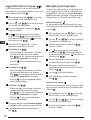
Subtracting 2 Measurements
You can subtract one measurement from another
(Figure
J
).
1.
Point the tool's laser (Figure
A
1
) toward a wall
or object, and not toward anyone's eyes.
2.
Press (Figure
A
3
) to turn the tool on and
display the red laser dot.
3.
Make sure the tool position setting (Figure
E
4
)
is correct for taking the measurement.
4.
If is not already displayed as the current
function (Figure
E
5
), click the current function
icon and then select
from the list of
functions (Figure
G
1
).
5.
Select - to indicate that you want to subtract one
measurement from another.
6.
Point the tool's laser toward the wall or object
whose distance you need to measure
(Figure
J
1
).
7.
Press to measure the distance from the tool
to the wall or object.
8.
Point the tool's laser toward the next wall or object
(Figure
J
2
).
9.
Press to measure the distance and subtract it
from the previous measurement.
10.
View the difference between the two
measurements at the bottom of the screen
(Figure
J
3
).
Measuring Continuously
To take a series of measurements as you move
around, change to Continuous Measure mode
(Figure
C
).
1.
Point the tool's laser (Figure
A
1
) toward a wall
or object, and not toward anyone's eyes.
2.
Press (Figure
A
3
) to turn the tool on and
display the red laser dot.
3.
Make sure the tool position setting (Figure
E
4
)
is correct for taking the measurement.
4.
If is not already displayed as the current
function (Figure
E
5
), click the current function
icon and then select
from the list of
functions (Figure
G
1
).
5.
Point the tool's laser (Figure
A
1
) toward
the wall or object whose distance you need to
measure (Figure
C
1
).
6.
At the bottom of the screen, view the current
measurement (Figure
C
2
), which will keep
changing as you move the tool.
7.
To take the current measurement (from the tool to
the wall or object) and exit Continuous Measure
mode, press
.
To take a new measurement, press
to move the
current measurement up to the previous line on the
screen. Then repeat steps 4-8.
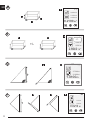
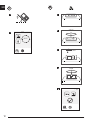
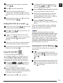
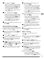
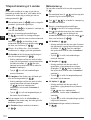
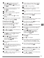
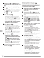
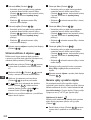
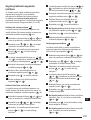
Measuring Area
1.
Point the tool's laser (Figure
A
1
) toward a wall
or object, and not toward anyone's eyes.
2.
Press (Figure
A
3
) to turn the tool on and
display the red laser dot.
3.
Make sure the tool position setting (Figure
E
4
)
is correct for taking the measurement.
4.
If is not already displayed as the current
function (Figure
E
5
), click the current function
icon and then select
from the list of functions
(Figure
G
1
).
5.
Measure the width (Figure
K
1
).
• Position the tool at one end of the wall, floor,
or object and point the laser dot across the
width. (Figure
K
1
shows where to position
the tool if you are measuring from the bottom
of the tool.)
• Press
to display the width measurement at
the top of the screen.
Strona jest ładowana ...

16
GB
7.
Measure the height (Figure
M
3
).
• Positon the tool at one end of the object and
point the laser dot across the height.
(Figure
M
3
shows where to position the
tool if you are measuring from the bottom of
the tool).
• Press
to display the height measurement
on the third line of the screen.
8.
View the Volume measurement at the bottom of
the screen (Figure
M
4
).
Adding/Subtracting 2 Volumes
You can measure the volume of room or object
and then add it to, or subtract it from, the volume of
another room or object (Figure
N
).
1.
Point the tool's laser (Figure
A
1
) toward a wall
or object, and not toward anyone's eyes.
2.
Press (Figure
A
3
) to turn the tool on and
display the red laser dot.
3.
Make sure the tool position setting (Figure
E
4
)
is correct for taking the measurement.
4.
If is not already displayed as the current
function (Figure
E
5
), click the current function
icon and then select
from the list of
functions (Figure
G
2
).
5.
Click + to add, or - to subtract, the volumes of two
objects.
6.
Measure the width (Figure
N
1
).
• Position the tool at one end of the object and
point the laser dot across the width.
(Figure
N
1
shows where to position the
tool if you are measuring from the bottom of
the tool.)
• Press
to display the width measurement at
the top of the screen.
7.
Measure the length (Figure
N
2
).
• Position the tool at one end of the object and
point the laser dot across the length. (Figure
N
2
shows where to position the tool if you are
measuring from the bottom of the tool.)
• Press
to display the length measurement on
the second line of the screen.
8.
Measure the height (Figure
N
3
).
• Position the tool at one end of the object and
point the laser dot across the height. (Figure
N
3
shows where to position the tool if you are
measuring from the bottom of the tool).
• Press
to display the height measurement on
the third line of the screen.
9.
Follow the same steps to measure the width,
length, and height of the second room or object.
10.
View the Volume measurement at the bottom of
the screen (Figure
N
4
).
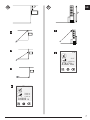
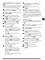
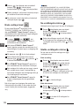
Measuring the Height of a Tall Object
If you need to measure the height of a tall object
(e.g., a tall building), you can calculate the height
based on the distance to 1 point or the distances
from the same point to 2 points on the object. The
tool will use the Pythagorean Theorem (C
2
=A
2
+B
2
) to
calculate the height.
Distance to 1 Point
You can use the distance to one point on a wall
or object (Indirect Height) to determine its height
(Figure
O
).
1.
Point the tool's laser (Figure
A
1
) toward a wall
or object, and not toward anyone's eyes.
2.
Press (Figure
A
3
) to turn the tool on and
display the red laser dot.
3.
Make sure the tool position setting (Figure
E
4
)
is correct for taking the measurement.
4.
If is not already displayed as the current
function (Figure
E
5
), click the current function
icon and then select
from the list of functions
(Figure
G
2
).
5.
Position the tool opposite the bottom of the
vertical height to be measured (Figure
O
1
).
6.
Point the laser toward the highest point of the
building or object whose height you need to
measure (Figure
O
1
).
7.
Press to measure the distance.
8.
View the height measurement at the bottom of the
screen (Figure
O
2
).
Strona jest ładowana ...

18
GB
Measuring from a Tripod
If you are placing the tool on a tripod to measure
the height of a tall building, follow these steps
(Figure
S
).
1.
Screw the 1/4-20" hole on the back of the tool
onto the 1/4-20" connection on the top of your
tripod (Figure
S
1
).
2.
Point the tool's laser (Figure
A
1
) toward a wall
or object, and not toward anyone's eyes.
3.
Press (Figure
A
3
) to turn the tool on and
display the red laser dot.
4.
Make sure the tool position setting (Figure
E
4
)
is
to measure from the tripod connection.
5.
If is not already displayed as the current
function (Figure
E
5
), click the current function
icon and then select
from the list of functions
(Figure
G
3
).
6.
Point the laser at the lowest point of the wall or
object whose height you need to measure
(Figure
S
2
).
7.
Press to take the measurement.
8.
Point the laser at other points on the wall or object
(Figure
S
3
).
9.
When ready, press to take the measurement.
10.
On the bottom line of the screen, view the height
of the wall or object (Figure
S
4
).
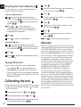
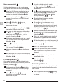
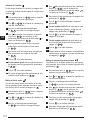
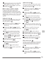
Positioning Studs
a
a
When you are framing a wall, use the Stakeout
feature to easily mark the position of each stud
(Figure
U
).
1.
Point the tool's laser (Figure
A
1
) toward a wall
or object, and not toward anyone's eyes.
2.
Press (Figure
A
3
) to turn the tool on and
display the red laser dot.
3.
Make sure the tool position setting (Figure
E
4
)
is set to to measure from the back of the tool.
4.
If
a
a
is not already displayed as the current
function (Figure
E
5
), click the current function
icon and then select
a
a
from the list of functions
(Figure
G
3
).
5.
Determine the distance between each stud, for
example, 12".
6.
Click
+
and
-
until the top number on the
screen is set to the distance from the right edge
of one stud to the left edge of the next (e.g., 12")
(Figure
U
1
).
7.
Line up the back of the tool with the right edge of
the last stud that is nailed in (Figure
U
2
).
8.
Press to start measuring the distance as you
slowly move the tool to the right.
9.
Continue moving the tool to the right until the
bottom number on the screen is 0.00 in
(Figure
U
3
).
10.
Press to stop measuring.
11.
Using a pencil, mark the location where the left
edge of the stud should be nailed into the wall
frame.
12.
Nail the left edge of the stud at the marked
location.
13.
For each remaining stud in the wall frame, repeat
steps 7-12 (Figure
U
4
).
Measuring an Angle
If you need to determine the angle at which
something is positioned, use the tool to measure
that angle.
1.
Point the tool's laser (Figure
A
1
) toward a wall
or object, and not toward anyone's eyes.
2.
Press (Figure
A
3
) to turn the tool on and
display the red laser dot.
3.
Make sure the tool position setting (Figure
E
4
)
is correct for taking the measurement.
4.
If is not already displayed as the current
function (Figure
E
5
), click the current function
icon and then select
from the list of functions
(Figure
G
2
).
Strona jest ładowana ...

20
GB
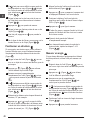
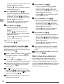
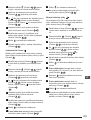
Clearing the Tool's Memory
You can clear one or more measurements that are
currently in the tool's memory.
Clearing a Measurement
1.
If is not already displayed as the current
function (Figure
E
5
), click the current function
icon and then select
from the list of functions
(Figure
G
3
).
2.
Click or to scroll through the
measurements that have been stored in the
tool's memory (up to 20) until you display the
measurement to be deleted.
3.
Click .
4.
Click to delete the measurement.
Clearing All Memory
1.
If is not already displayed as the current
function (Figure
E
5
), click the current function
icon and then select
from the list of functions.
2.
Click .
3.
Click to delete ALL measurements from the
tool's memory.
Turning Off the Tool
The tool can be turned off in either of these ways:
• Press and hold
for 10 seconds. When you
release
after 10 seconds, the tool will turn off.
• If you do not use the tool for the number of seconds
(30, 60, or 300) you have set for auto turn off, it will
automatically turn off.
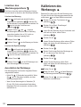
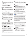
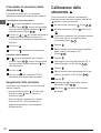
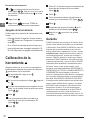
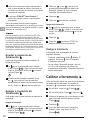
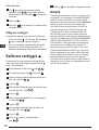
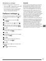
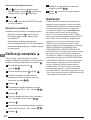
Calibrating the tool
Please note that if you do not position the tool correctly
for each step of the calibration process,
will appear
in red on the screen.
1.
On the touchscreen, click (Figure
C
8
).
2.
On the Settings Menu (Figure
H
), click .
3.
Place the tool with the front screen facing upward
on a flat, level surface (Figure
W
1
).
4.
Press .
5.
While the tool is still laying on the level surface,
turn the tool 180° (Figure
W
2
).
6.
Press .
7.
Flip the long side of the tool 90° so it is laying on
its side (Figure
W
3
).
8.
Press .
9.
While the tool is still laying on its side, turn the
tool 180° (Figure
W
4
).
10.
Press .
11.
Make sure appears on the tool's screen
(Figure
W
5
).
12.
Click to return to the previous screen.
Warranty
STANLEY warrants this product for a period of Two (2)
years against deficiencies in material and workmanship.
This LIMITED WARRANTY does not cover products
that are improperly used, abused, altered, or repaired.
Please go to www.2helpU.com for more information or
return instructions. Unless otherwise noted, STANLEY
will repair without cost, any STANLEY product found
to be defective, including parts and labor charges, or
at STANLEY’s option, will replace such tools or refund
the purchase price, less the amount for depreciation,
in exchange for the defective tool. THIS LIMITED
WARRANTY EXCLUDES ALL INCIDENTAL OR
CONSEQUENTIAL DAMAGES. Some states do
not allow the exclusion or limitation of incidental or
consequential damages, so these limitations may not
apply to you. This TWO YEAR LIMITED WARRANTY
gives you specific legal rights that may vary from state
to state. In addition to the warranty, STANLEY Lasers
are covered by: 30-Day Money Back Guarantee. If you
are not completely satisfied with the performance of
your STANLEY Laser for any reason, you can return it
within 30 days from the date of purchase with a receipt
for a full refund.

21
GB
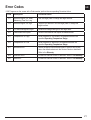
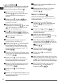
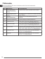
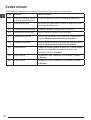
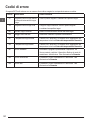
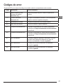
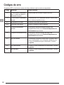
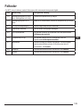
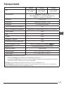
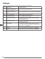
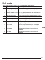
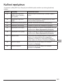
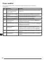
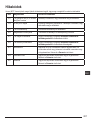
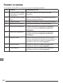
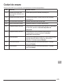
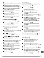
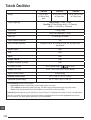
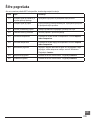
Error Codes
If INFO appears on the screen with a Code number, perform the corresponding Corrective Action.
Code Description Corrective Action
101 Received Signal Too Weak,
Measuring Time Too Long
Use the target plate or change the target surface.
102 Received Signal Too High Target is too reective. Use the target plate or change the
target surface.
201 Too Much Background Light Reduce the background light on the target area.
202 Laser Beam Interrupted Remove the obstacle and repeat the measurement.
301 Temperature Too High Allow the device to cool down to a temperature within the
specied Operating Temperature Range.
302 Temperature Too Low Allow the device to warm up to a temperature within the
specied Operating Temperature Range.
401 Hardware Error Switch the device on/off several times. If the error still occurs,
return the defective device to the Service Center or distributor.
Refer to the Warranty.
402 Unknown Error Contact the Service Center or distributor. Refer to the Warranty.
500 Data Error Contact the Service Center or distributor. Refer to the Warranty.

22
GB
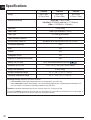
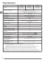
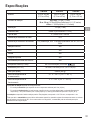
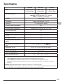
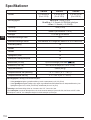
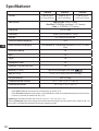
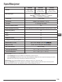
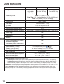
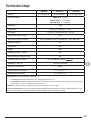
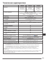
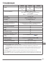
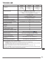
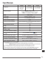
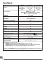
Specications
TLM165S TLM165SI TLM330S
Range 6in to 165ft
(0.15m to 50m)
6in to 197ft
(0.15m to 60m)
6in to 330ft
(0.15m to 100m)
Measuring Accuracy
1
up to 10m: 1/16in (1.5mm)
10m-30m: 0.078/5/64in) additional (+/- 0.15mm/m)
>30m: +/- 0.002in/ft (+/- 0.2mm/m)
Resolution
2
1/16in (1mm)
Laser Class Class 2 (IEC/EN60825-1: 2014)
Laser Type ≤ 1.0mW @ 620-690nm
Laser Automatic Switch-off 30s
Unit Automatic Switch-off By default, 90s. User can set to 30s, 60s, or 300s
Continuous Measuring Yes
Area Yes
Volume Yes
Pythagoras 2-Point Yes
Endpiece to measure from corners
3
Yes
Battery Life (3 x AAA)
Up to 3000 Measurements (2500 with
)
Dimension (H x D x W) 4.72 x 1.91 x 1.02in (120 x 48.5 x 26mm)
Weight (with Batteries) 9.88oz (280g)
Storage Temperature Range 14° F ~ 140° F (-10° C ~ +60 C)
Operating Temperature Range 32° F ~ 104° F (0° C ~ +40° C)
1
Measuring Accuracy depends on the current conditions:
• Under favorable conditions (good target surface and room temperature), up to 33ft (10m).
• Under unfavorable conditions (bright sunlight, a very weak reecting target surface, or large temperature uctuations), the
error can increase to ± 0.002 in/ft (± 0.2mm/m) for distances over 33ft (10m).
2
Resolution is the nest measurement you can see. In inches, that is 1/16". In mm, that is 1mm.
3
Flip open the endpiece at the bottom of the tool when you need to t the tool into corners or grooves that are not at 180° angles. If
a corner is at 90°, the endpiece can be used to hold the tool up against something.
Strona jest ładowana ...
Strona jest ładowana ...
Strona jest ładowana ...

D
26
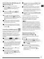
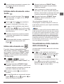
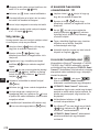
2.
Drücken Sie auf (Abbildung
A
3
), um
das Werkzeug einzuschalten und den roten
Laserpunkt anzuzeigen.
3.
Stellen Sie sicher, dass die Wahl der
Werkzeugposition (Abbildung
E
4
) die richtige
für die Durchführung der Messung ist.
4.
Wenn nicht bereits als aktuelle Funktion
angezeigt wird (Abbildung
E
5
), drücken Sie
auf das aktuelle Funktionssymbol und wählen Sie
aus der Liste der Funktionen aus
(Abbildung
G
1
).
5.
Richten Sie den Laser des Werkzeugs
(Abbildung
A
1
) auf die Wand oder das Objekt,
deren bzw. dessen Entfernung Sie messen wollen
(Abbildung
B
1
).
6.
Drücken Sie auf , um den Abstand von dem
Werkzeug zu der Wand oder dem Objekt zu
messen.
7
Lesen Sie unten auf dem Bildschirm den aktuellen
Messwert ab (Abbildung
B
2
).
Für eine weitere Messung drücken Sie auf
, um
das aktuelle Messergebnis in die vorherige Zeile des
Bildschirms zu verschieben. Wiederholen Sie dann
die Schritte 3-6.
2 Messungen addieren
Sie können zwei Messungen addieren, um eine
Gesamtmessung der beiden Strecken zu erhalten
(Abbildung
I
).
1.
Richten Sie den Laser des Werkzeugs
(Abbildung
A
1
) auf eine Wand oder einem
Gegenstand und nicht auf die Augen von
Personen.
2.
Drücken Sie auf (Abbildung
A
3
), um
das Werkzeug einzuschalten und den roten
Laserpunkt anzuzeigen.
3.
Stellen Sie sicher, dass die Wahl der
Werkzeugposition (Abbildung
E
4
) die richtige
für die Durchführung der Messung ist.
4.
Wenn nicht bereits als aktuelle Funktion
angezeigt wird (Abbildung
E
5
), drücken Sie
auf das aktuelle Funktionssymbol und wählen
Sie
aus der Liste der Funktionen aus
(Abbildung
G
1
).
5.
Wählen Sie +, um anzugeben, dass Sie
Messungen addieren möchten.
6.
Richten Sie den Laser des Werkzeugs auf die
erste Wand oder das erste Objekt, deren bzw.
dessen Abstand Sie messen wollen
(Abbildung
I
1
).
7.
Drücken Sie auf , um den Abstand von dem
Werkzeug zu der Wand oder dem Objekt zu
messen.
8.
Richten Sie den Laser des Werkzeugs auf
die nächste Wand oder das nächste Objekt
(Abbildung
I
2
).
9.
Drücken Sie auf , um die Strecke zu messen
und zu der vorherigen Messung zu addieren.
10.
Lesen Sie die Summe der beiden Messungen
unten auf dem Bildschirm ab (Abbildung
I
3
).
2 Messungen subtrahieren
Sie können ein Messergebnis von einem anderen
subtrahieren (Abbildung
J
).
1.
Richten Sie den Laser des Werkzeugs
(Abbildung
A
1
) auf eine Wand oder einem
Gegenstand und nicht auf die Augen von
Personen.
2.
Drücken Sie auf (Abbildung
A
3
), um
das Werkzeug einzuschalten und den roten
Laserpunkt anzuzeigen.
3.
Stellen Sie sicher, dass die Wahl der
Werkzeugposition (Abbildung
E
4
) die richtige
für die Durchführung der Messung ist.
4.
Wenn nicht bereits als aktuelle Funktion
angezeigt wird (Abbildung
E
5
), drücken Sie
auf das aktuelle Funktionssymbol und wählen
Sie
aus der Liste der Funktionen aus
(Abbildung
G
1
).
5.
Wählen Sie -, um anzugeben, dass Sie eine
Messung von einer anderen subtrahieren
möchten.
6.
Richten Sie den Laser des Werkzeugs auf die
Wand oder das Objekt, deren bzw. dessen
Entfernung Sie messen möchten
(Abbildung
J
1
).
Strona jest ładowana ...
Strona jest ładowana ...
Strona jest ładowana ...
Strona jest ładowana ...
Strona jest ładowana ...
Strona jest ładowana ...
Strona jest ładowana ...
Strona jest ładowana ...
Strona jest ładowana ...
Strona jest ładowana ...
Strona jest ładowana ...
Strona jest ładowana ...
Strona jest ładowana ...
Strona jest ładowana ...
Strona jest ładowana ...
Strona jest ładowana ...
Strona jest ładowana ...
Strona jest ładowana ...
Strona jest ładowana ...
Strona jest ładowana ...
Strona jest ładowana ...
Strona jest ładowana ...
Strona jest ładowana ...
Strona jest ładowana ...
Strona jest ładowana ...
Strona jest ładowana ...
Strona jest ładowana ...
Strona jest ładowana ...
Strona jest ładowana ...
Strona jest ładowana ...
Strona jest ładowana ...
Strona jest ładowana ...
Strona jest ładowana ...
Strona jest ładowana ...
Strona jest ładowana ...
Strona jest ładowana ...
Strona jest ładowana ...
Strona jest ładowana ...
Strona jest ładowana ...
Strona jest ładowana ...
Strona jest ładowana ...
Strona jest ładowana ...
Strona jest ładowana ...
Strona jest ładowana ...
Strona jest ładowana ...
Strona jest ładowana ...
Strona jest ładowana ...
Strona jest ładowana ...
Strona jest ładowana ...
Strona jest ładowana ...
Strona jest ładowana ...
Strona jest ładowana ...
Strona jest ładowana ...
Strona jest ładowana ...
Strona jest ładowana ...
Strona jest ładowana ...
Strona jest ładowana ...
Strona jest ładowana ...
Strona jest ładowana ...
Strona jest ładowana ...
Strona jest ładowana ...
Strona jest ładowana ...
Strona jest ładowana ...
Strona jest ładowana ...
Strona jest ładowana ...
Strona jest ładowana ...
Strona jest ładowana ...
Strona jest ładowana ...
Strona jest ładowana ...
Strona jest ładowana ...
Strona jest ładowana ...
Strona jest ładowana ...
Strona jest ładowana ...
Strona jest ładowana ...
Strona jest ładowana ...
Strona jest ładowana ...
Strona jest ładowana ...
Strona jest ładowana ...
Strona jest ładowana ...
Strona jest ładowana ...
Strona jest ładowana ...
Strona jest ładowana ...
Strona jest ładowana ...
Strona jest ładowana ...
Strona jest ładowana ...
Strona jest ładowana ...
Strona jest ładowana ...
Strona jest ładowana ...
Strona jest ładowana ...
Strona jest ładowana ...
Strona jest ładowana ...
Strona jest ładowana ...
Strona jest ładowana ...
Strona jest ładowana ...
Strona jest ładowana ...
Strona jest ładowana ...
Strona jest ładowana ...
Strona jest ładowana ...
Strona jest ładowana ...
Strona jest ładowana ...
Strona jest ładowana ...
Strona jest ładowana ...
Strona jest ładowana ...
Strona jest ładowana ...
Strona jest ładowana ...
Strona jest ładowana ...
Strona jest ładowana ...
Strona jest ładowana ...
Strona jest ładowana ...
Strona jest ładowana ...
Strona jest ładowana ...
Strona jest ładowana ...
Strona jest ładowana ...
Strona jest ładowana ...
Strona jest ładowana ...
Strona jest ładowana ...
Strona jest ładowana ...
Strona jest ładowana ...
Strona jest ładowana ...
Strona jest ładowana ...
Strona jest ładowana ...
Strona jest ładowana ...
Strona jest ładowana ...
Strona jest ładowana ...
Strona jest ładowana ...
Strona jest ładowana ...
Strona jest ładowana ...
Strona jest ładowana ...
Strona jest ładowana ...
Strona jest ładowana ...
Strona jest ładowana ...
Strona jest ładowana ...
Strona jest ładowana ...
Strona jest ładowana ...
Strona jest ładowana ...
Strona jest ładowana ...
Strona jest ładowana ...
Strona jest ładowana ...
Strona jest ładowana ...
Strona jest ładowana ...
Strona jest ładowana ...
Strona jest ładowana ...
Strona jest ładowana ...
Strona jest ładowana ...
Strona jest ładowana ...
Strona jest ładowana ...
Strona jest ładowana ...
Strona jest ładowana ...
Strona jest ładowana ...
Strona jest ładowana ...
Strona jest ładowana ...
Strona jest ładowana ...
Strona jest ładowana ...
Strona jest ładowana ...
Strona jest ładowana ...
Strona jest ładowana ...
Strona jest ładowana ...
Strona jest ładowana ...
Strona jest ładowana ...
Strona jest ładowana ...
Strona jest ładowana ...
Strona jest ładowana ...
Strona jest ładowana ...
Strona jest ładowana ...
Strona jest ładowana ...
Strona jest ładowana ...
Strona jest ładowana ...
Strona jest ładowana ...
Strona jest ładowana ...
Strona jest ładowana ...
Strona jest ładowana ...
Strona jest ładowana ...
Strona jest ładowana ...
Strona jest ładowana ...
Strona jest ładowana ...
Strona jest ładowana ...
Strona jest ładowana ...
Strona jest ładowana ...
Strona jest ładowana ...
Strona jest ładowana ...
Strona jest ładowana ...
Strona jest ładowana ...
Strona jest ładowana ...
Strona jest ładowana ...
Strona jest ładowana ...
Strona jest ładowana ...
Strona jest ładowana ...
Strona jest ładowana ...
Strona jest ładowana ...
Strona jest ładowana ...
Strona jest ładowana ...
Strona jest ładowana ...
Strona jest ładowana ...
Strona jest ładowana ...
Strona jest ładowana ...
Strona jest ładowana ...
Strona jest ładowana ...
Strona jest ładowana ...
Strona jest ładowana ...
Strona jest ładowana ...
Strona jest ładowana ...
Strona jest ładowana ...
Strona jest ładowana ...
Strona jest ładowana ...
Strona jest ładowana ...
Strona jest ładowana ...
Strona jest ładowana ...
Strona jest ładowana ...
Strona jest ładowana ...
Strona jest ładowana ...
Strona jest ładowana ...
Strona jest ładowana ...
Strona jest ładowana ...
Strona jest ładowana ...
Strona jest ładowana ...
Strona jest ładowana ...
Strona jest ładowana ...
Strona jest ładowana ...
Strona jest ładowana ...
Strona jest ładowana ...
Strona jest ładowana ...
Strona jest ładowana ...
Strona jest ładowana ...
Strona jest ładowana ...
Strona jest ładowana ...
Strona jest ładowana ...
Strona jest ładowana ...
Strona jest ładowana ...
Strona jest ładowana ...
Strona jest ładowana ...
Strona jest ładowana ...
Strona jest ładowana ...
Strona jest ładowana ...
Strona jest ładowana ...
Strona jest ładowana ...
Strona jest ładowana ...
Strona jest ładowana ...
Strona jest ładowana ...
Strona jest ładowana ...
Strona jest ładowana ...
Strona jest ładowana ...
Strona jest ładowana ...
Strona jest ładowana ...
Strona jest ładowana ...
Strona jest ładowana ...
Strona jest ładowana ...
Strona jest ładowana ...
Strona jest ładowana ...
Strona jest ładowana ...
Strona jest ładowana ...
Strona jest ładowana ...
Strona jest ładowana ...
Strona jest ładowana ...
Strona jest ładowana ...
Strona jest ładowana ...
Strona jest ładowana ...
Strona jest ładowana ...
Strona jest ładowana ...
Strona jest ładowana ...
Strona jest ładowana ...
Strona jest ładowana ...
Strona jest ładowana ...
Strona jest ładowana ...
Strona jest ładowana ...
Strona jest ładowana ...
Strona jest ładowana ...
Strona jest ładowana ...
Strona jest ładowana ...
Strona jest ładowana ...
Strona jest ładowana ...
Strona jest ładowana ...
Strona jest ładowana ...
Strona jest ładowana ...
Strona jest ładowana ...
Strona jest ładowana ...
Strona jest ładowana ...
Strona jest ładowana ...
Strona jest ładowana ...
Strona jest ładowana ...
Strona jest ładowana ...
Strona jest ładowana ...
Strona jest ładowana ...
Strona jest ładowana ...
Strona jest ładowana ...
Strona jest ładowana ...
Strona jest ładowana ...
Strona jest ładowana ...
Strona jest ładowana ...
Strona jest ładowana ...
Strona jest ładowana ...
Strona jest ładowana ...
Strona jest ładowana ...
Strona jest ładowana ...
Strona jest ładowana ...
Strona jest ładowana ...
Strona jest ładowana ...
Strona jest ładowana ...
Strona jest ładowana ...
Strona jest ładowana ...
Strona jest ładowana ...
Strona jest ładowana ...
Strona jest ładowana ...
Strona jest ładowana ...
Strona jest ładowana ...
Strona jest ładowana ...
Strona jest ładowana ...
Strona jest ładowana ...
Strona jest ładowana ...
Strona jest ładowana ...
Strona jest ładowana ...
Strona jest ładowana ...
Strona jest ładowana ...
-
 1
1
-
 2
2
-
 3
3
-
 4
4
-
 5
5
-
 6
6
-
 7
7
-
 8
8
-
 9
9
-
 10
10
-
 11
11
-
 12
12
-
 13
13
-
 14
14
-
 15
15
-
 16
16
-
 17
17
-
 18
18
-
 19
19
-
 20
20
-
 21
21
-
 22
22
-
 23
23
-
 24
24
-
 25
25
-
 26
26
-
 27
27
-
 28
28
-
 29
29
-
 30
30
-
 31
31
-
 32
32
-
 33
33
-
 34
34
-
 35
35
-
 36
36
-
 37
37
-
 38
38
-
 39
39
-
 40
40
-
 41
41
-
 42
42
-
 43
43
-
 44
44
-
 45
45
-
 46
46
-
 47
47
-
 48
48
-
 49
49
-
 50
50
-
 51
51
-
 52
52
-
 53
53
-
 54
54
-
 55
55
-
 56
56
-
 57
57
-
 58
58
-
 59
59
-
 60
60
-
 61
61
-
 62
62
-
 63
63
-
 64
64
-
 65
65
-
 66
66
-
 67
67
-
 68
68
-
 69
69
-
 70
70
-
 71
71
-
 72
72
-
 73
73
-
 74
74
-
 75
75
-
 76
76
-
 77
77
-
 78
78
-
 79
79
-
 80
80
-
 81
81
-
 82
82
-
 83
83
-
 84
84
-
 85
85
-
 86
86
-
 87
87
-
 88
88
-
 89
89
-
 90
90
-
 91
91
-
 92
92
-
 93
93
-
 94
94
-
 95
95
-
 96
96
-
 97
97
-
 98
98
-
 99
99
-
 100
100
-
 101
101
-
 102
102
-
 103
103
-
 104
104
-
 105
105
-
 106
106
-
 107
107
-
 108
108
-
 109
109
-
 110
110
-
 111
111
-
 112
112
-
 113
113
-
 114
114
-
 115
115
-
 116
116
-
 117
117
-
 118
118
-
 119
119
-
 120
120
-
 121
121
-
 122
122
-
 123
123
-
 124
124
-
 125
125
-
 126
126
-
 127
127
-
 128
128
-
 129
129
-
 130
130
-
 131
131
-
 132
132
-
 133
133
-
 134
134
-
 135
135
-
 136
136
-
 137
137
-
 138
138
-
 139
139
-
 140
140
-
 141
141
-
 142
142
-
 143
143
-
 144
144
-
 145
145
-
 146
146
-
 147
147
-
 148
148
-
 149
149
-
 150
150
-
 151
151
-
 152
152
-
 153
153
-
 154
154
-
 155
155
-
 156
156
-
 157
157
-
 158
158
-
 159
159
-
 160
160
-
 161
161
-
 162
162
-
 163
163
-
 164
164
-
 165
165
-
 166
166
-
 167
167
-
 168
168
-
 169
169
-
 170
170
-
 171
171
-
 172
172
-
 173
173
-
 174
174
-
 175
175
-
 176
176
-
 177
177
-
 178
178
-
 179
179
-
 180
180
-
 181
181
-
 182
182
-
 183
183
-
 184
184
-
 185
185
-
 186
186
-
 187
187
-
 188
188
-
 189
189
-
 190
190
-
 191
191
-
 192
192
-
 193
193
-
 194
194
-
 195
195
-
 196
196
-
 197
197
-
 198
198
-
 199
199
-
 200
200
-
 201
201
-
 202
202
-
 203
203
-
 204
204
-
 205
205
-
 206
206
-
 207
207
-
 208
208
-
 209
209
-
 210
210
-
 211
211
-
 212
212
-
 213
213
-
 214
214
-
 215
215
-
 216
216
-
 217
217
-
 218
218
-
 219
219
-
 220
220
-
 221
221
-
 222
222
-
 223
223
-
 224
224
-
 225
225
-
 226
226
-
 227
227
-
 228
228
-
 229
229
-
 230
230
-
 231
231
-
 232
232
-
 233
233
-
 234
234
-
 235
235
-
 236
236
-
 237
237
-
 238
238
-
 239
239
-
 240
240
-
 241
241
-
 242
242
-
 243
243
-
 244
244
-
 245
245
-
 246
246
-
 247
247
-
 248
248
-
 249
249
-
 250
250
-
 251
251
-
 252
252
-
 253
253
-
 254
254
-
 255
255
-
 256
256
-
 257
257
-
 258
258
-
 259
259
-
 260
260
-
 261
261
-
 262
262
-
 263
263
-
 264
264
-
 265
265
-
 266
266
-
 267
267
-
 268
268
-
 269
269
-
 270
270
-
 271
271
-
 272
272
-
 273
273
-
 274
274
-
 275
275
-
 276
276
-
 277
277
-
 278
278
-
 279
279
-
 280
280
-
 281
281
-
 282
282
-
 283
283
-
 284
284
-
 285
285
-
 286
286
-
 287
287
-
 288
288
-
 289
289
-
 290
290
-
 291
291
-
 292
292
-
 293
293
-
 294
294
-
 295
295
-
 296
296
-
 297
297
-
 298
298
-
 299
299
-
 300
300
-
 301
301
-
 302
302
-
 303
303
-
 304
304
-
 305
305
-
 306
306
-
 307
307
-
 308
308
-
 309
309
-
 310
310
-
 311
311
-
 312
312
-
 313
313
-
 314
314
-
 315
315
-
 316
316
-
 317
317
-
 318
318
-
 319
319
-
 320
320
-
 321
321
-
 322
322
-
 323
323
-
 324
324
-
 325
325
-
 326
326
-
 327
327
-
 328
328
-
 329
329
-
 330
330
-
 331
331
-
 332
332
-
 333
333
-
 334
334
-
 335
335
-
 336
336
-
 337
337
-
 338
338


Stanley STHT1-77140N Instrukcja obsługi
- Typ
- Instrukcja obsługi
- Ten podręcznik jest również odpowiedni dla
w innych językach
- čeština: Stanley STHT1-77140N Uživatelský manuál
- español: Stanley STHT1-77140N Manual de usuario
- italiano: Stanley STHT1-77140N Manuale utente
- Deutsch: Stanley STHT1-77140N Benutzerhandbuch
- eesti: Stanley STHT1-77140N Kasutusjuhend
- slovenčina: Stanley STHT1-77140N Používateľská príručka
- svenska: Stanley STHT1-77140N Användarmanual
- português: Stanley STHT1-77140N Manual do usuário
- français: Stanley STHT1-77140N Manuel utilisateur
- Türkçe: Stanley STHT1-77140N Kullanım kılavuzu
- English: Stanley STHT1-77140N User manual
- dansk: Stanley STHT1-77140N Brugermanual
- русский: Stanley STHT1-77140N Руководство пользователя
- suomi: Stanley STHT1-77140N Ohjekirja
- Nederlands: Stanley STHT1-77140N Handleiding
- română: Stanley STHT1-77140N Manual de utilizare