
ARIES MUSIC SYNTHESIZER-SYSTEM 300
KEYBOARD SYSTEM ASSEMBLY
AR-311 KEYBOARD * AR-313 KEYBOARD INTERFACE * AR-320 CASE
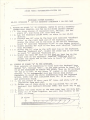
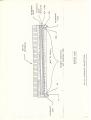
I WIRING OF 30ARD "A" TO KEYBOARD. REFER TO AR-311 KEYBOARD
CONNECTIONS DRAWING, AND THE AR-313 BOARD LAYOUT CRAWING.
( ) 1. Cut three pieces of insulated wire, 48"each, and one
p i e c e 1 0 " , a n d s t r i p 1 / 4 " f r o m e a c h e n d . . :
( ) 2. Lay the keyboard, upside down, as shown in the AR-311
( ) 3. ConneSt'one 48" wire to the buss wire labelled "keyboard
voice" on the right hand end of the keyboard. Solder.
Solder the other end to the hole in the'AR-313 Interface
board "A" labelled "Keyboard Voice" on .the layout drawing.
( ) 4. Solder another 48" wire to the buss wire labelled "Keyboard
Gate Switches".
( ) 5 Solder the 10" wire to the left most lug on the keyboard,
labelled "Keyboard Low". Solder the other end to the hole
in board "A" labelled "Keyboard Lo".
( ) 6 Solder the next 48" wire to the next to last lug on the
right side of the keyboard, labelled "Keyboard High".
Solder the other end to the hole in board "A" labelled
"Keyboard Hi".
II WIRING OF 30ARD "B" TO THE KEYBOARD.
This consists of connecting 61 wires from the keyboard lugs^
marked "Kl", through "K61" , to the same points on Board B .
IT IS NOT NECESSARY TO FOLLOW ANY ORDER. That is, K2 on Board
"B" may go to K37, or any other "K" number on the keyboard.
However, it is recommended that you follow this wiring
procedure to avoid the wires interfering with the keyboard
action. NOTE: Use thin insulated wire; No. 22 or smaller,
a n d p r e f e r a b l y s o l i d . ,
( ) 1. Cut ten pieces of wire, each 29" long, and strip 1/4 of
insulation from each end.
( ) 2 Solder one of these wires to the lug marked Kl on the
keyboard (see keyboard drawing) NOTE: The first lug is not
Kl!
3. Solder the other wires to the next nine lugs (K2 thru K10)
4. Gr asp all 1 0 wi res togethe r, and p ull the m t ightl y to th e
l e f t , a s s h o w n . . „ _ _ „ _ _ _ /
(
( )
( )
xt~xt~k>~
-xp p
keyboard connections
■ v*—c—0—-tr
/
7
■ xr
y
i
/-

■y
SYSTEM 30 0
KEYBOARD SYSTEM ASSEMBLY
( ) 5. Starting from the end near Kl, twist the bundle
slightly. While pulling, twist all the way to the
end.
( ) 6. Find the wire furthest in from the end of the bundle,
' and cut off all the others to be even with it.
( ) 7. Cut ten new-wires,, each 36'" long, and strip the ends.
( ) 3. "older these to the next ten lugs (Kll thru K20).
( ).9. Keeping this bundle separate, pull to the left and
twist, like the first 10.
( )10. Cut off the other ends to be even, as before.
( )11. Cut ten new wires, each 43" long, and repeat for the
lugs K21 thru K3 0. You should now have three bundles.
MOTE: They- should come to different lengths when pulled
to the left.
( )12. Cut ten more wires, each 50" long, and repeat for K31
thru K40.
( )13. Cut ten more wires, each 57" long, and repeat for K41
thru K50.
( )14. Cut eleven finally, each 64" long, and repeat for K51
thru K61.Notice the lug between K60 and 63 ; do njjt
j mistake this for K61?
( 515. You should now Have"six neat bundles of wire.Thay should h&
held together about every 6" with tape, lacing, or cable
ties if possible, and pushed down into theucorner of
the keyboard case. NOW, WIRE TO BOARD "B".
( )16. Solder the ends of the longest bundle of wires (the lafct
one wired to the keyboard) to Board "B", in the holes
labelled K51 thru ?»G1 (see Board "B" assembly drawing) .
NOTE: Run wires through from the component side of :-v.e
board."B".
( )17. Solder the next longest bundle into holes for K41 thru
K50.
( )18. Repeat for K31 thru K40.
( )19. Repeat for K21 thru K30.
( )20. Repeat for Kll thru K20.
( )21. Repeat for Kl thru K10.
THIS COMPLETES WIRING OF KEYBOARD TO BOARD "B" .
III. POWER CONNECTIONS
You may use any type of wire or connector you wish for the +ijv,
-15v +5v, and ground If you'ire going to use the keyboard with
the ARIES^SYSTEM 300 Power Supply, however, there is a male
plug furnished which fits the power supply.
Recommended Procedure: ■
i ) 1 Cut four pieces of insulated wire, each 6 feet tor
longer, if desired to allow keyboard to be further from
synthesizer). Strip 1/4" insulation from each end.
( ) 2 Solder one wire to Board "A", +15v. (The wire you left
bare above the board.) Solder the other end to pin 1 of the
male plug (standard octal base).
-2T
~\

a
"c
SYSTEM 300
KEYBOARD SYSTEM ASSEMBLY
-15v. Solder the other
+5v. Solder the other
( ) 3. Solder the second wire to Board "A",
end to pin 3 of the plug.
( ) 4. Solder the third wire to Board "A'
end to pin 5 of the plug.
( ) 5. Solder the last wire toBoard "A",ground, ( to bare part
of wire above board).Solder other end to pin 7 of plug.
( ) 6. Twist or harness the four wires together neatly.
THIS COMPLETES ALL WIRING !9E YOUR ARIES KEYBOARD SYSTEM.
PROCEED NOW TO MOUNT THE BOARDS AND PANEL TO THE KEYBOARD CASE.
( ) 1. If the case is already assembled, remove the top
cover (long wood strip) and the panel board. If the case is
not assembled," assemble everything except Kpanel board
and top cover. (See AR-320 Case instructions.)
( ) 2. Push the wired panel through the hole in the panel board ,
(panel must be on side of board with bevelled outerholes).'
J. ) 3. Fasten panel down to board with four wood screws,
( ) 4. Mount Board "A" on bottom of panel board: Push four
wood screws through Board "A" from component side. Place
four spacers on screws AFTER pushing them through board.
Screw into bottom of panel board, roughly in center of
board. NOTE: No holes have been provided on panel board
on some units.
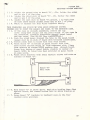
( ) 5. Mount small brackets with small machine screws and nuts on
corners of Board "B":
©
Board "B"
FOIL SIDE
( ) 6. Hold Board "B" as shown above. Bend wire bundles down flat
against board; and toward bottom left on above drawing as
shown. .
( ) 7. Screw Board "B" brackets to keyboard case.in the four
rounded slots provided.
-3-

* * S Y S T E M 3 0 0
KEYBOARD SYSTEM ASSEMBLY
J
( ) 8. VERY IMPORTANT! Check that no wires interfere with
keyboard contacts" action. Tuck wires into bottom
corner of keyboard case.It is advisable to fasten
the bundle down with INSULATED-. staples, cement, or
' : . , t a p e .
( ) 9. Complete case assembly by fastening down panel board
and top cover
(
n
7
'<;
■<■:
I
-4-

M
I
Ct
<
i l
! (
I
CD
ID LO
V - ^
o
< I
3
o
o
0
oc
T
LL
M
LU
a
CO
or
I
8
H
O
cq
CO
o
O
a
rr
<
o
03
>-
LU
I
<
-
 1
1
-
 2
2
-
 3
3
-
 4
4
-
 5
5


w innych językach
- English: Aries 300 Series
Inne dokumenty
-
Yamaha P2050 Instrukcja obsługi
-
-
-
-
-
Yamaha CS6R Instrukcja obsługi
-
-
-
-