Novus NVIP-2VE-4231 PIR instrukcja
- Kategoria
- Kamery ochrony
- Typ
- instrukcja

Quick start guide
NVIP-2VE-4231/PIR

NVIP-2VE-4231/PIR Quick start guide version 1.1
All rights reserved © AAT SYSTEMY BEZPIECZEŃSTWA Sp. z o.o.
2
SAFEGUARDS AND WARNINGS
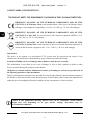
THE PRODUCT MEETS THE REQUIREMENTS CONTAINED IN THE FOLLOWING DIRECTIVES:
Information
The device, as an element of a professional CCTV system used for supervision and control, is not
intended for self-installation in households by people without specialist knowledge.
Exclusion of liability in case of damage data on disks or other devices or media:
The manufacturer is not liable in the event of damage or loss of data contained on disks or other
devices or media during the operation of the Product.
Obligation to consult with the Manufacturer before performing an activity not provided for in
the operating manual or other documents:
Before performing an action that is not provided for in the Product manual, other documents attached to
the Product or does not result from the normal purpose of the Product, please contact the Manufacturer
under the pain of excluding the Producer's liability for the consequences of such an action.
DIRECTIVE 2014/30/EU OF THE EUROPEAN PARLIAMENT AND OF THE
COUNCIL of 26 February 2014 on the harmonization of the laws of the Member States
relating to electromagnetic compatibility (OJ L 96, 29.3.2014, p. 79–106, with changes)
DIRECTIVE 2012/19/EU OF THE EUROPEAN PARLIAMENT AND OF THE
COUNCIL of 4 July 2012 on waste electrical and electronic equipment (WEEE) (OJ L
197, 24.7.2012, p. 38–71, with changes)
DIRECTIVE 2011/65/EU OF THE EUROPEAN PARLIAMENT AND OF THE
COUNCIL of 8 June 2011 on the restriction of the use of certain hazardous substances in
electrical and electronic equipment (OJ L 174, 1.7.2011, p. 88–110, with changes)
Pictures in this publication showing camera views can be simulations. Actual camera
images may vary depending on the type, model, settings, observation area, or
environmental conditions.

NVIP-2VE-4231/PIR Quick start guide version 1.1
All rights reserved © AAT SYSTEMY BEZPIECZEŃSTWA Sp. z o.o.
3
SAFEGUARDS AND WARNINGS
WARNING!
THE KNOWLEDGE OF THIS MANUAL IS AN NECESSARY CONDITION OF PROPER USE OF
THE DEVICE. PLEASE READ IT BEFORE INSTALLING AND OPERATING THE DEVICE.
WARNING!
USER IS NOT ALLOWED TO DISASSEMBLE THE CASING AS THERE ARE NO USER
-SERVICEABLE PARTS INSIDE THIS UNIT. ONLY AUTHORIZED SERVICE PERSONNEL
MAY OPEN THE UNIT
1. Prior to undertaking any action please consult the following manual and read all the safety and
operating instructions before starting the device.
2. Please keep this manual for the lifespan of the device in case referring to the contents of this manual
is necessary;
3. All the safety precautions referred to in this manual should be strictly followed, as they have a direct
influence on user’s safety and durability and reliability of the device;
4. All actions conducted by the servicemen and users must be accomplished in accordance with the
user’s manual;
5. The device should be disconnected from power sources during maintenance procedures;
6. Usage of additional devices and components neither provided nor recommended by the producer is
forbidden;
7. Mounting the device in places where proper ventilation cannot be provided (e. g. closed lockers etc.)
is not recommended since it may lead to heat build-up and damaging the device itself as a
consequence;
8. Mounting the camera on unstable surface or using not recommended mounts is forbidden.
Improperly mounted camera may cause a fatal accident or may be seriously damaged itself. The
camera must be mounted by qualified personnel with proper authorization, in accordance with this
user’s manual.
9. Device should be supplied only from a power sources whose parameters are in accordance with
those specified by the producer in the camera technical datasheet. Therefore, it is forbidden to
supply the camera from a power sources with unknown parameters, unstable or not meeting
producer’s requirements;
Due to the product being constantly enhanced and optimized, certain parameters and functions
described in the manual in question may change without further notice.
We strongly suggest visiting the www.novuscctv.com/en website in order to access the newest full
manual

NVIP-2VE-4231/PIR Quick start guide version 1.1
All rights reserved © AAT SYSTEMY BEZPIECZEŃSTWA Sp. z o.o.
4
FOREWORD INFORMATION
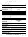
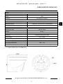
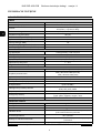
1. TECHNICAL SPECIFICATION
IMAGE
Image Sensor 2 MPX CMOS sensor 1/2.7” SmartSens
Number of Eecve Pixels 1920 (H) x 1080 (V)
Min. Illuminaon 0.1 lx/F1.2 - color mode,
0 lx (IR on) - B/W mode
Electronic Shuer auto/manual: 1/5 s ~ 1/20000 s
Digital Slow Shuer (DSS) up to 1/5 s
Wide Dynamic Range (WDR) yes
Digital Noise Reducon (DNR) 2D, 3D
Defog Funcon (F-DNR) yes
Back Light Compensaon (BLC) yes
Reducon of image icker (Anicker) yes
LENS
Lens Type xed focal, f=2.8 mm/F2.2
DAY/NIGHT
Switching Type mechanical IR cut lter
Switching Mode auto, manual, me
Switching Delay 1 ~ 36 s
Visible Light Sensor yes
NETWORK
Stream Resoluon 1920 x 1080 (Full HD), 640 x 480 (VGA)
Frame Rate 30 fps for 1920 x 1080 (Full HD),
20 fps for 640 x 480 (VGA)
Mulstreaming Mode 2 streams
Video/Audio Compression H.264, H.265/G.711
Number of Simultaneous Connecons max. 10
Bandwidth 40 Mb/s in total
Network Protocols Support HTTP, TCP/IP, IPv4, HTTPS, FTP, DHCP, DNS, DDNS, NTP, RTSP,
RTP, UPnP, SMTP
ONVIF Protocol Support Prole S/G
Camera Conguraon from Internet Explorer, Firefox browser
languages: Polish, English, Russian, and others
Compable Soware NMS
OTHER FUNCTIONS
Privacy Zones 4 video mask type: single color
Moon Detecon yes
PIR detector range up to 7 m
Image Processing 180˚ image rotaon, vercal ip, horizontal ip
Prealarm/Postalarm up to 5 s/up to 30 s
System Reacon to Alarm Events e-mail with aachment, saving le on FTP server, saving le
on SD card, saving in the cloud storage
Restoring default sengs via web browser, using reset buon

NVIP-2VE-4231/PIR Quick start guide version 1.1
All rights reserved © AAT SYSTEMY BEZPIECZEŃSTWA Sp. z o.o.
5
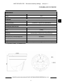
FOREWORD INFORMATION
1.1. Camera dimensions (in millimeters)
IR LED
LED Number 2
Range 30 m
Smart IR yes (hardware support)
INTERFACES
Audio Input/Output built-in microphone
Network Interface 1 x Ethernet - RJ-45 interface, 10/100 Mbit/s
Memory Card Slot microSD - capacity up to 256GB
INSTALLATION PARAMETERS
Dimensions (mm) 100 (Ф) x 90 (H)
Weight 0.43 kg
Degree of Protecon IP 66 (details in the user’s manual)
Enclosure vandalproof aluminium, white
Power Supply PoE, 12 VDC
Surge protecon TVS 4000 V
Power Consumpon 1.5 W, 4 W (IR on)
Operang Temperature -30°C ~ 55°C
Humidity max. 95%, relave (non-condensing)

NVIP-2VE-4231/PIR Quick start guide version 1.1
All rights reserved © AAT SYSTEMY BEZPIECZEŃSTWA Sp. z o.o.
6
Caution:
If the device was brought from a room with a lower temperature, wait until it reaches the
temperature of the room in which it is to work. Do not switch the device immediately after
bringing from a cooler place. The condensation of water vapor can cause short circuits and
consequently damage the device.
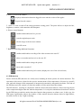
2. START-UP AND INITIAL CONFIGURATION
Before starting the device familiarize yourself with the description and the role of particular
inputs, outputs and adjusting elements that the device is equipped with.
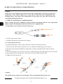
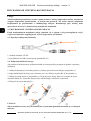
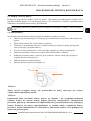
2.1. Description of the camera's electrical connectors
1. 12VDC camera power socket
2. 100 Mb/s Ethernet port (hermetic RJ-45 socket)
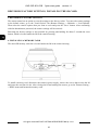
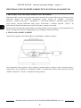
2.2. Connecting ethernet cable
To maintain hermeticity network cable connection, follow the instructions below:
1. Unscrew the nut (b) from the connector cover (a), mount the sealing ring on the socket (c)
2. Route the network cable through the components (a) and (b). Plug the RJ-45 connector into the
socket (c)
3. Screw the connector cover (a) on the socket (c). Inside the upper part of the connector cover (a) push
in to the stop the seal of the cable (d) - the seal is cut to insert on the network cable.
4. Tighten up to the stop nut (b)
Caution:
The 12VDC power connector is not hermetic. The user should seal them on his own.
START-UP AND INITIAL CONFIGURATION
1
2
b a
b
a
c
d

NVIP-2VE-4231/PIR Quick start guide version 1.1
All rights reserved © AAT SYSTEMY BEZPIECZEŃSTWA Sp. z o.o.
7
2.3. "Two way power" function
The camera is equipped with the "Two way power" function. When the camera is connected to the PoE
switch, 12VDC is available in the 12V camera power socket. This allows user to power the receiver
with low power consumption, e.g. a microphone, from the camera power socket.
2.4. Camera mounting
To mount a camera please follow the instructions below:
• Remove the retaining ring (A) by turning it counter-clockwise
• Remove the camera cover (B), remove the camera from the base
• Put the bracket to the wall in a desired mounting place (with cable hole). Taking the bracket’s
base screw holes as a pattern, mark future drilling holes for screws.
• Drill holes in accordance with previously done markings and base hole placement.
• Mount the camera base using the supplied plugs and screws.
• Connect the camera cables, put camera on the base, attach the cover (B) and pre-tighten the
retaining ring (A)
• Adjust camera position.
• Tighten to the stop retaining ring (A)
Caution:
Please note that the wall or ceiling must have enough strength to support the camera.
Caution:
The declared degree of protection of the camera relates to its housing and does not take into
account the possibility of moisture infiltration into the interior of the camera by connecting
cables. Connection cables protection through i.e. sealing up is the responsibility of the camera
installer. The manufacturer is not liable for any damages to the camera caused as a result of
failing in performing that activity by installer, which also means that camera damaged in that
way is not subject to warranty repairs.
START-UP AND INITIAL CONFIGURATION
A
B
The maximum power consumption of the device using the “Two way power” function is 3W.

NVIP-2VE-4231/PIR Quick start guide version 1.1
All rights reserved © AAT SYSTEMY BEZPIECZEŃSTWA Sp. z o.o.
8
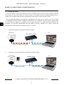
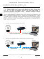
2.5. Starting the camera
To start the camera, connect the Ethernet cable to the RJ45 network socket of the IP camera, and the
other end to the network switch. As a power source, it is possible to use an external stabilized power
supply with parameters that meet the requirements of the camera or PoE network switch.
The recommended method of starting and configuring the IP camera is to connect it to a PC or laptop
in a dedicated network switch to which no other devices are connected. In case of power supply from
an external power supply, it is enough to use any network switch or a cable connected directly to the
computer. For network configuration data (IP address, gateway, netmask etc.), please contact the
administrator of the network in which the device is to work.
• Connection using network switch with PoE support
• Connection using external power supply and network switch
START-UP AND INITIAL CONFIGURATION
PC IP camera
Power and data transmission Data transmission
PoE network switch
IP camera
Data transmission Data transmission
Network switch PC

NVIP-2VE-4231/PIR Quick start guide version 1.1
All rights reserved © AAT SYSTEMY BEZPIECZEŃSTWA Sp. z o.o.
9
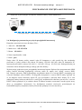
• Connection using the camera's external power supply and an Ethernet crossover cable
2.6. Parameter configuration using a web browser
The default network settings for camera are:
1. IP address= 192.168.1.200
2. Network mask - 255.255.255.0
3. Gateway - 192.168.1.1
4. User name - root
5. Password - pass
Knowing the camera’s IP address you need to appropriately set PC IP address, so the two devices can
operate in one network subnet ( e.g. for IP 192.168.1.1, appropriate address for the camera ranges from
192.168.1.2 to 192.168.1.254, for example 192.168.1.60). It is not allowed to set the same addresses for
camera and PC computer
You can either set a network configuration (IP address, gateway, net mask, etc.) of NOVUS IP camera
yourself or select DHCP mode (DHCP server is required in this method in target network) by using
web browser or by NMS software. When you use DHCP server check IP address lease and its linking
with camera MAC address to avoid changing or losing IP address during device operation or network/
DHCP server breakdown. You have to remember to use a new camera IP address after changing
network parameters.
After network setting configuration has been done, the camera can be connected to a target network.
START-UP AND INITIAL CONFIGURATION
PC IP camera
Data transmission - Ethernet crossover cable

NVIP-2VE-4231/PIR Quick start guide version 1.1
All rights reserved © AAT SYSTEMY BEZPIECZEŃSTWA Sp. z o.o.
10
START-UP AND INITIAL CONFIGURATION
2.7. Security recommendations for network architecture and configuration
WARNING!
Below are shown security recommendations for network architecture and configuration
of CCTV systems that are connected to the Internet to reduce the risk
of unauthorized interference with the system by a third party.
1. Absolutely change the default passwords and user names (if the device gives this possibility) of
all applied network devices (recorders, cameras, routers, network switches, etc.) to the
severely complexity password. Use lowercase and uppercase letters, numbers, and special characters
if there is such possibility.
2. Depending on the available functionality in the order to restrict access to the used network devices at
the administrator account level, it is recommended to configure the users accounts accordingly.
3. Do not use DMZ function (Demilitarized zone) in your router. Using that function you open the
access to recorder system from the Internet on all ports, which gives possibility for an unauthorized
interference with the system.
Instead of DMZ use port forwarding redirect only the ports which are necessary for the performance
of the connection (detailed information about ports of communication in different models of recorders,
cameras, etc. can be found in the operating instructions).
4. Use routers with firewall function and make sure it is enabled and properly configured.
5. It is recommended to change the default network communication port numbers of used devices
if there is such possibility.
6. If used network devices has a UPnP feature and it is not used, turn it off.
7. If used network devices has a P2P feature and it is not used, turn it off.
8. If used network devices support HTTPS protocol for connection, it is recommended to use it.
9. If used network devices support IP filtering for authorized connections function, it is recommended
to use it.
10. If used recorder has two network interfaces it is recommended to use both of them to physically
separate network for cameras and network for Internet connection. The only device in the system,
accessible from Internet will be recorder - there will be no physically access directly to any camera.

NVIP-2VE-4231/PIR Quick start guide version 1.1
All rights reserved © AAT SYSTEMY BEZPIECZEŃSTWA Sp. z o.o.
11
3. NETWORK CONNECTION USING WEB BROSWER
3.1. Recommended PC specification for web browser connections
The following requirements apply to the connection with the IP camera assuming smooth video display
at the maximum resolution.
1. CPU Intel Core i3 3GHz or newer
2. RAM Memory min. 8 GB
3. Graphic card (any Nvidia GeForce 512MB Ram or equivalent)
4. OS Windows 8/8.1/10
5. Network card 100/1000 Mb/s
3.2. First connection to the camera via a web browser
Enter the IP address of the camera in the address bar of the web browser. After connection, the
following will be displayed: the administrator password definition window and then the security
question window, allowing you to regain access to the camera in the event of forgetting the
administrator password, without the need to reset.
Defining the administrator password
When connecting to the camera for the first time, the administrator password definition window is
displayed.
Enter the password for the administrator account in the "New Password" field, and then repeat for
confirmation in the "Confirm Password" field. The strength of the password is indicated on the
"Password Strength" indicator, and the requirements for its creation can be seen in the pop-up window
that shows up by hovering over the question mark symbol.
NETWORK CONNECTION USING WEB BROWSER

NVIP-2VE-4231/PIR Quick start guide version 1.1
All rights reserved © AAT SYSTEMY BEZPIECZEŃSTWA Sp. z o.o.
12
After defining the administrator password, the password recovery question selection window is
displayed.
To activate the security questions, select the "Security Question Configuration" option. Then select the
questions from the "Security Question" lists and enter your own answers in the “Answer” fields.
After making the necessary changes, save them by pressing the "OK" button. The camera confirms the
correctness of the operations by displaying a confirmation window. After pressing the "OK" button in
the confirmation window, the login window to the web panel of the camera is displayed.
NETWORK CONNECTION USING WEB BROWSER
It is not mandatory to activate security questions. This step can be skipped by pressing the "OK"
button without selecting "Security Question Configuration", or by pressing the "Cancel" button.
However, in this case, the password recovery option is not available and the only way to restore
access to the camera in case the password is lost is to use the button reset.
It is obligatory to answer all the questions. Selected questions and answers should be stored in a
place protected against unauthorized access. After saving the answers, they cannot be changed,
and giving new ones is possible after restoring the factory settings.
Since the camera does not analyze the sense of the answer, but only remembers it, it can be any
string of characters. The same answer can be given to each of the questions.

NVIP-2VE-4231/PIR Quick start guide version 1.1
All rights reserved © AAT SYSTEMY BEZPIECZEŃSTWA Sp. z o.o.
13
Administrator password recovery
To regain access to the camera if you forget the password, click on the "Recover password" link in the
lower right corner of the login window. The password recovery window is displayed, in which user
must enter the answers provided during the configuration of the answer in the appropriate fields, and
then set a new password.
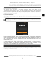
Login to the camera
To log in to the camera, enter the administrator account name and password in the login window.
After logging in using the Internet Explorer browser, the camera can display a message about the need
to install "SurveillancePluginV2.exe" plug-in, necessary to display video (this message appears if the
system was not previously installed the plug-in or if the plug-in is present, but it is in the wrong
version).
In this case, click on the "Download and install the player" link and follow the installer's instructions.
After the installation is complete, refresh the browser window. After these steps, the camera image
should appear in the live view window.
If the plug-in installation process is interrupted by Windows Security, allow the plug-in to install and
run.
NETWORK CONNECTION USING WEB BROWSER
At the top of the login window there is a language selection list for the camera menu.

NVIP-2VE-4231/PIR Quick start guide version 1.1
All rights reserved © AAT SYSTEMY BEZPIECZEŃSTWA Sp. z o.o.
14
USING AND CONFIGURING
4. USING AND CONFIGURING
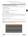
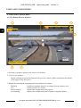
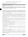
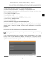
4.1. The Remote Preview Interface
1. Selecting a stream to display in the remote view window.
2. Live Preview window.
Double-clicking the left mouse button on the preview window enables and disables the display
of the image on the full screen.
3. Buttons for selecting the operating mode and configure the camera:
Playback - enables the playback panel of recordings from the memory card
Live - enables preview live stream
Remote Setting - displays the configuration panel camera
Local Setting - displays the configuration panel of paths to snapshots folders
7
6
3 4
1
5
2

NVIP-2VE-4231/PIR Quick start guide version 1.1
All rights reserved © AAT SYSTEMY BEZPIECZEŃSTWA Sp. z o.o.
15
4. Icon to access to the camera:
5. Allows to turn on and off the image parameter setting panel. The panel allows to adjust the hue,
brightness, contrast, color saturation and sharpness.
6. Picture control buttons:
7. Buttons controlling additional functions:
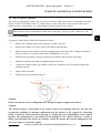
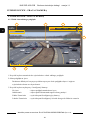
4.2 PIR function
Passive infrared (PIR) detectors are widely used, including in alarm systems for motion detection. The
operation of the sensor is based on the precise measurement of the temperature of objects in a specific
area, and each change of this temperature is interpreted as motion by integrated electronics. The task of
the PIR detector in the camera is to limit the number of false motion detection alarms.
The PIR detector, working in conjunction with the motion detection function, detects moving objects
with a temperature higher than the ambient temperature. It is only the simultaneous detection of motion
by the PIR detector and the motion detection function that generates an alarm event. In this way, the
PIR sensor significantly reduces the number of false motion detection alarms related to light flashes,
snowfall, insects or day / night switching.
USING AND CONFIGURING
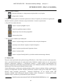
- sets the original aspect ratio
- fits the image to the browser window
- sets full screen
- enables and disables the live preview
- displays information about the logged in user and the version of the applet
- logout from the camera
- enables and disables recording of the video stream to the user PC
- takes a screenshot and saves it to the user PC
- enables and disables enlarge the picture
- turns audio on and off
- enables and disables the pixel counter (displays the size of the selected area)

NVIP-2VE-4231/PIR Quick start guide version 1.1
All rights reserved © AAT SYSTEMY BEZPIECZEŃSTWA Sp. z o.o.
16
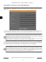
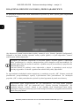
5. RESTORING FACTORY SETTINGS
The camera menu has an option to reset the settings to the factory values. To restore the camera settings
to the default values, go to the "Load Default" tab (Remote Settings -> Maintain -> Load Default).
Then select the camera options that you want to reset and press the "Save" button. After confirming
with the administrator password, the camera settings will be restored.
Restoring the factory settings is also possible by pressing and holding for about 5 seconds the reset
button, which is located under the lid in the camera housing.
6. INSTALLING A MEMORY CARD
The microSD memory card slot is located under the lid in the camera housing.
To install a memory card, disconnect the camera's power supply, remove the screws that secures the lid
and insert the card into its slot. After closing the lid and starting the camera, go to the "Remote Setting -
> HDD" menu and format the memory card.
RESTORING FACTORY SETTINGS, INSTALLING THE SD CARD

NVIP-2VE-4231/PIR Quick start guide version 1.1
All rights reserved © AAT SYSTEMY BEZPIECZEŃSTWA Sp. z o.o.
17

8.11.2021 TF, MK v1.1
AAT SYSTEMY BEZPIECZEŃSTWA Sp. z o.o.
431 Pulawska St., 02-801 Warsaw, Poland
tel.: +4822 546 0 546, [email protected]
www.novuscctv.com

Skrócona instru kc ja obsłu gi
NVIP-2VE-4231/PIR

NVIP-2VE-4231/PIR Skrócona instrukcja obsługi wersja 1.1
Wszelkie prawa zastrzeżone © AAT SYSTEMY BEZPIECZEŃSTWA Sp. z o.o.
2
UWAGI I OSTRZEŻENIA
PRODUKT SPEŁNIA WYMAGANIA ZAWARTE W DYREKTYWACH:
Informacja
Urządzenie, jako element profesjonalnego systemu telewizji dozorowej służącego do nadzoru
i kontroli, nie jest przeznaczone do samodzielnego montażu w gospodarstwach domowych przez osoby
nie posiadające specjalistycznej wiedzy.
Wyłączenie odpowiedzialności w przypadku uszkodzenia danych zawartych na dyskach lub
innych urządzeniach lub nośnikach:
Producent nie ponosi odpowiedzialności w razie uszkodzenia lub utraty w trakcie eksploatacji Produktu
danych zawartych na dyskach lub innych urządzeniach lub nośnikach.
Obowiązek konsultowania się z Producentem przed wykonaniem czynności nieprzewidzianej
instrukcją obsługi albo innymi dokumentami:
Przed wykonaniem czynności, która nie jest przewidziana dla danego Produktu w instrukcji obsługi,
innych dokumentach dołączonych do Produktu lub nie wynika ze zwykłego przeznaczenia Produktu,
należy, pod rygorem wyłączenia odpowiedzialności Producenta za następstwa takiej czynności,
skontaktować się z Producentem.
DYREKTYWA PARLAMENTU EUROPEJSKIEGO I RADY 2014/30/UE z dnia 26
lutego 2014 r. w sprawie harmonizacji ustawodawstw państw członkowskich odnoszących
się do kompatybilności elektromagnetycznej (Dz.U. L 096 z 29.3.2014, s. 79—106, z
późniejszymi zmianami) – zwana Dyrektywa EMC
DYREKTYWA PARLAMENTU EUROPEJSKIEGO I RADY 2012/19/UE z dnia 4
lipca 2012 r. w sprawie zużytego sprzętu elektrycznego i elektronicznego (WEEE) Dz.U. L
96 z 29.3.2014, str. 79—106, z późniejszymi zmianami) – zwana Dyrektywa WEEE
DYREKTYWA PARLAMENTU EUROPEJSKIEGO I RADY 2011/65/UE
z dnia 8 czerwca 2011 r. w sprawie ograniczenia stosowania niektórych niebezpiecznych
substancji w sprzęcie elektrycznym i elektronicznym (Dz.U. L 174 z 1.7.2011, str. 88—110,
z późniejszymi zmianami) - zwana Dyrektywa RoHS
Zamieszczone w niniejszej publikacji zdjęcia przedstawiające obrazy z kamer mogą być
symulacjami. Rzeczywiste obrazy z kamer mogą się różnić, w zależności od typu, modelu,
ustawień, obszaru obserwacji lub warunków zewnętrznych.
Strona się ładuje...
Strona się ładuje...
Strona się ładuje...
Strona się ładuje...
Strona się ładuje...
Strona się ładuje...
Strona się ładuje...
Strona się ładuje...
Strona się ładuje...
Strona się ładuje...
Strona się ładuje...
Strona się ładuje...
Strona się ładuje...
Strona się ładuje...
Strona się ładuje...
Strona się ładuje...
-
 1
1
-
 2
2
-
 3
3
-
 4
4
-
 5
5
-
 6
6
-
 7
7
-
 8
8
-
 9
9
-
 10
10
-
 11
11
-
 12
12
-
 13
13
-
 14
14
-
 15
15
-
 16
16
-
 17
17
-
 18
18
-
 19
19
-
 20
20
-
 21
21
-
 22
22
-
 23
23
-
 24
24
-
 25
25
-
 26
26
-
 27
27
-
 28
28
-
 29
29
-
 30
30
-
 31
31
-
 32
32
-
 33
33
-
 34
34
-
 35
35
-
 36
36


Novus NVIP-2VE-4231 PIR instrukcja
- Kategoria
- Kamery ochrony
- Typ
- instrukcja
w innych językach
- English: Novus NVIP-2VE-4231 PIR User guide
Powiązane artykuły
-
Novus NVIP-2VE-4201/PIR Instrukcja obsługi
-
-
-
-
-
-
-
-
-