Yamaha AX16 Instrukcja obsługi
- Kategoria
- Miksery audio
- Typ
- Instrukcja obsługi
Ten podręcznik jest również odpowiedni dla


COMPLIANCE INFORMATION STATEMENT
(DECLARATION OF CONFORMITY PROCEDURE)
Responsible Party: YAMAHA CORPORATION OF AMERICA
Address: 6600 Orangethorpe Avenue, Buena Park, Calif. 90620 U.S.A.
Telephone: 1-714-522-9011
FAX: 1-714-739-2680
Type of Equipment: AUDIO EXPANSION CARD
Model Name: AX16-AT
This device complies with Part 15 of the FCC Rules.
Operation is subject to the following conditions:
1) this device may not cause harmful interference, and
2) this device must accept any interference received including interference that may cause undesired operation.
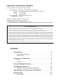
Contents
Introduction . . . . . . . . . . . . . . . . . . . . . . . . . . . . . . . . . 4
System Requirements . . . . . . . . . . . . . . . . . . . . . . . . . . . . . . 4
PCI or ISA? . . . . . . . . . . . . . . . . . . . . . . . . . . . . . . . . . . . . . . . 4
Controls & Connections . . . . . . . . . . . . . . . . . . . . . . . . 5
Rear . . . . . . . . . . . . . . . . . . . . . . . . . . . . . . . . . . . . . . . . . . . . . 5
Internal . . . . . . . . . . . . . . . . . . . . . . . . . . . . . . . . . . . . . . . . . . 6
System Hookup Overview . . . . . . . . . . . . . . . . . . . . . . . 8
Installing the AX16-AT . . . . . . . . . . . . . . . . . . . . . . . . . 9
Fitting the ISA-bus Mounting Bracket . . . . . . . . . . . . . . . . 10
Selecting the I/O Source for the DS2416 . . . . . . . . . . . 11
Specifications . . . . . . . . . . . . . . . . . . . . . . . . . . . . . . . . 12
Dimensions . . . . . . . . . . . . . . . . . . . . . . . . . . . . . . . . . . . . . . 13
FCC INFORMATION (U.S.A.)
1. IMPORTANT NOTICE: DO NOT MODIFY THIS UNIT! This product, when installed as indicated in the instructions contained in this manual, meets FCC
requirements. Modifications not expressly approved by Yamaha may void your authority, granted by the FCC, to use the product.
2. IMPORTANT: When connecting this product to accessories and/or another product use only high quality shielded cables. Cable/s supplied with this product MUST
be used. Follow all installation instructions. Failure to follow instructions could void your FCC authorization to use this product in the USA.
3. NOTE: This product has been tested and found to comply with the requirements listed in FCC Regulations, Part 15 for Class “B” digital devices. Compliance with
these requirements provides a reasonable level of assurance that your use of this product in a residential environment will not result in harmful interference with
other electronic devices. This equipment generates/uses radio frequencies and, if not installed and used according to the instructions found in the users manual, may
cause interference harmful to the operation of other electronic devices. Compliance with FCC regulations does not guarantee that interference will not occur in all
installations. If this product is found to be the source of interference, which can be determined by turning the unit “OFF” and “ON”, please try to eliminate the
problem by using one of the following measures: Relocate either this product or the device that is being affected by the interference. Utilize power outlets that are on
different branch (circuit breaker or fuse) circuits or install AC line filter/s. In the case of radio or TV interference, relocate/reorient the antenna. If the antenna lead-in
is 300 ohm ribbon lead, change the lead-in to coaxial type cable. If these corrective measures do not produce satisfactory results, please contact the local retailer
authorized to distribute this type of product. If you can not locate the appropriate retailer, please contact Yamaha Corporation of America, Electronic Service
Division, 6600 Orangethorpe Ave, Buena Park, CA 90620
The above statements apply ONLY to those products distributed by Yamaha Corporation of America or its subsidiaries.

3
AX16-AT—Owner’s Manual
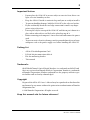
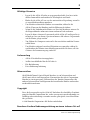
Important Notices
• Do not place the AX16-AT in an area subject to excessive heat, direct sun-
light, excessive humidity, or dust.
• Keep the AX16-AT inside its antistatic bag until you are ready to install it.
• To prevent handling damage, hold the AX16-AT by the edges or bracket.
• If you accidentally touch the card edge connections, remove any finger-
prints using a dry tissue.
• Do not place objects on top of the AX16-AT, and do not put it down in a
place where other objects are likely to be placed on top of it.
• Before removing your computer’s cover, turn it off and remove the power
cord.
• To prevent static electricity damage, touch a grounded metal part of your
computer, such as the power supply case, before handling the AX16-AT.
Packing List
• AX16-AT Audio Expansion Card
• DS2416 20-pin connection cable x2
• ISA-bus mounting bracket
• This manual
Trademarks
ADAT MultiChannel Optical Digital Interface is a trademark and ADAT and
Alesis are registered trademarks of Alesis Corporation. Yamaha is a trademark
of Yamaha Corporation. All other trademarks are the property of their respec-
tive holders and are hereby acknowledged.
Copyright
No part of the AX16-AT
Owner’s Manual
may be reproduced or distributed in
any form or by any means without the prior written authorization of Yamaha
Corporation, Inc.
© 1998 Yamaha Corporation. All rights reserved.
Keep this manual safe for future reference!

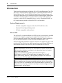
4
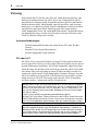
Introduction
AX16-AT—Owner’s Manual
Introduction
Thank you for purchasing the Yamaha AX16-AT Audio Expansion Card. The
AX16-AT is an ADAT format digital interface card for the Yamaha DS2416
Digital Mixing Card. Two ADAT MultiChannel Optical Digital inputs and
two outputs mean that up to 16 channels of ADAT format digital audio can be
transferred simultaneously between the DS2416 and an ADAT multitrack
recorder, or other ADAT-compatible device, such as a Yamaha 02R, 03D, or
01V digital mixing console with an ADAT I/O card installed.
System Requirements
• DS2416-compatible computer with a free PCI or ISA-bus slot
• Yamaha DS2416 Digital Mixing Card
• DS2416-compatible audio software
PCI or ISA?
The AX16-AT is set for installation in a PCI-bus slot, but can also be installed
in an ISA slot simply by swapping the supplied mounting bracket. Since
DS2416-compatible Apple Power Macintosh computers do not support ISA
bus, the AX16-AT must be used in a PCI slot with Power Macs. On
DS2416-compatible Windows computers, however, the AX16-AT can be used
in either a PCI or ISA-bus slot, which means that even if all your PCI slots are
taken and the only free slots are ISA, you can still install the AX16-AT.
Important: If you are using the DS2416 and AX16-AT in a Windows 95 or
Windows 98 computer, be sure to use DS2416 driver version V103 or later.
The latest driver software is available for free download from the Yamaha
Professional Audio Web site.
<http://www.yamaha.co.jp/product/proaudio/homeenglish/>
DS2416 driver version V102 or earlier does not support the AX16-AT
ADAT/THRU switch. However, it can be made to recognize the switch by
relaunching the DS2416-supporting audio software.
Important: When the DS2416’s internal Vari Pitch mode is used, the word-
clock, or sampling rate changes accordingly and some devices connected to
the AX16-AT for use as wordclock slaves may not be able to synchronize cor-
rectly. However, they may synchronize correctly at certain settings (resultant
sampling rates), but not others.

Controls & Connections
5
AX16-AT—Owner’s Manual
Controls & Connections
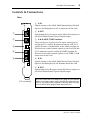
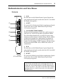
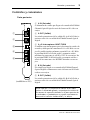
Rear
A
A IN
Signals arriving at this ADAT MultiChannel Optical Digital
input are fed through to the IO-A connector on this card.
B
A OUT
Signals from the IO-A outputs on the DS2416 are output via
this ADAT MultiChannel Optical Digital output.
C
A & B ADAT/THRU switches
These switches are used to select the input and output sig-
nals for the IO-A and IO-B connectors on this card. IO-A
and IO-B can be set individually. In the ADAT position, the
DS2416 receives and transmits signals via the A or B IN and
OUT connectors on this card. In the THRU position, the
DS2416 receives and transmits signals via the THRU A or B
connectors on this card.
D
B IN
Signals arriving at this ADAT MultiChannel Optical Digital
input are fed through to the IO-B connector on this card.
E
B OUT
Signals from the IO-B outputs on the DS2416 are output via
this ADAT MultiChannel Optical Digital output.
Note: Be aware that if the body of the plugs on your optical
cables is too large to pass easily through the expansion-slot
holes in the rear of your computer, the plugs may not plug
into the ADAT jacks properly and may come lose.
1
2
3
4
5
A
B
IN
IN
OUT
(PCI mounting)
OUT
ADAT
THRU

6
Controls & Connections
AX16-AT—Owner’s Manual
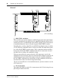
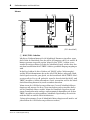
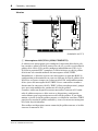
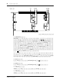
Internal
A
HALF/FULL switches
These switches are used to configure wordclock operation when the DS2416
is used as a wordclock slave and receives its wordclock from the AX16-AT. IO-
A and IO-B can be set individually. In the FULL position, the DS2416 derives
its wordclock from the source selected using the ADAT/THRU switches.
Normally, these switches should be set to HALF, the default setting, in which
case the DS2416’s wordclock source is always an ADAT IN connector regard-
less of the ADAT/THRU switch settings. This is convenient when switching
between the ADAT and THRU (AX44 or other device) connectors, because
you don’t have to change the wordclock settings.
When an external device connected to the A IN connector is used as the
wordclock master, that device must be turned on and configured correctly for
wordclock master operation. If, for some reason, the external wordclock is
lost, the THRU connectors are checked for a usable wordclock, and if one is
not found there either, the DS2416 stops functioning.
(To use an external device as the wordclock master, you must connect it to the
A IN connector.)
B
IO-A connector
This connector connects to the IO-A connector on the DS2416 using the sup-
plied 20-pin connection cable.
45231
A
A
A
[ THROUGH IO-A ]
THRU-A
B
B
THRU-B
B
[ THROUGH IO-B ]
[ THROUGH IO-B ]
B
B
B
[ THROUGH IO-A ]
A
A
A
IO-AIO-B
FULL
HALF
OFF
(PCI mounting)

Controls & Connections
7
AX16-AT—Owner’s Manual
C
IO-B connector
This connector connects to the IO-B connector on the DS2416 using the sup-
plied 20-pin connection cable.
D
THRU-A connector
This connector connects to the first AX44 Audio Expansion Unit using the
20-pin connection cable supplied with the AX44.
E
THRU-B connector
This connector connects to the second AX44 Audio Expansion Unit using the
20-pin connection cable supplied with the AX44.

8
System Hookup Overview
AX16-AT—Owner’s Manual
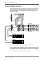
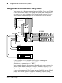
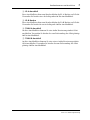
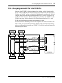
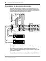
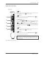
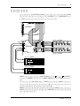
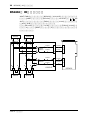
System Hookup Overview
The following diagram shows how the AX16-AT connects to the DS2416 and
AX44s. Also shown are two digital multitrack recorders with ADAT format
inputs and outputs for up to 16 channels of digital audio transfer between
them and the DS2416.
When using an ADAT, set the corresponding ADAT/THRU switch (A or B) to
ADAT. To use an AX44, set the switch to THRU.
In the system shown here, the DS2416, ADAT-A, or ADAT-B could be used as
the wordclock master. (Supporting software is required to set the wordclock.)
If an ADAT recorder is used as the wordclock master, turn on the ADAT first,
set its wordclock, and then set the DS2416 wordclock.
A
A
A
[ THROUGH IO-A ]
THRU-A
B
B
THRU-B
B
[ THROUGH IO-B ]
[ THROUGH IO-B ]
B
B
B
[ THROUGH IO-A ]
A
A
A
IO-AIO-B
FULL
HALF
OFF
IO
A
B
SI
SO
IO-A
IO-B
INPUT 1 2 3 4
1234
OUTPUT
POWER
LINE MIC
–10dBV –50dBV –10dBV –50dBV
LINE MIC
AX44
INPUT 1 2 3 4
1234
OUTPUT
POWER
LINE MIC
–10dBV –50dBV –10dBV –50dBV
LINE MIC
AX44
DS2416
AX16-AT
ADAT-A
IO-A
IN
OUT
IN
OUT
IO-A
THRU-A
THRU-B
IO-B
IO-B
ADAT-B
AX44-A
ADAT-B
ADAT-A
AX44-B

Installing the AX16-AT
9
AX16-AT—Owner’s Manual
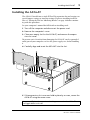
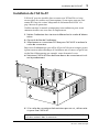
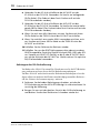
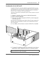
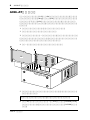
Installing the AX16-AT
The AX16-AT installs into a single PCI or ISA expansion slot and requires no
special jumper settings or interrupt settings. If you are installing in an ISA
slot, see “Fitting the ISA-bus Mounting Bracket” on page 10 before continu-
ing with this procedure.
See your computer’s manual for full details on installing cards.
1
Turn off the computer and disconnect the power cord.
2
Remove the computer’s cover.
3
Choose an empty slot for the AX16-AT, and remove the expan-
sion-slot cover.
To prevent static electricity from damaging the AX16-AT, touch a grounded
metal part of your computer, such as the power supply case, before handling
it.
4
Carefully align and insert the AX16-AT into the slot.
5
If the expansion-slot cover was held in place by a screw, secure the
AX16-AT using the same screw.
Important: Tighten the expansion-slot fixing screw so that the AX16-AT can-
not jiggle about in the slot.
A
A
THRU-A
B
THRU-B
[ THROUGH IO-B ]
B
B
[ THROUGH IO-A ]
A
A
A
IO-A
IO-B
FULL
HALF
OFF
OFF
PCI
ISA

10
Installing the AX16-AT
AX16-AT—Owner’s Manual
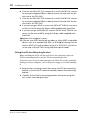
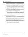
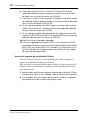
6
Connect the AX16-AT IO-A connector to the DS2416 IO-A connec-
tor using the supplied 20-pin cable (connect the end with the fer-
rite core to the DS2416).
7
Connect the AX16-AT IO-B connector to the DS2416 IO-B connec-
tor using the supplied 20-pin cable (connect the end with the fer-
rite core to the DS2416).
8
If you are using an AX44, connect the AX16-AT THRU-A connector
to the first AX44 using the 20-pin cable supplied with the AX44.
9
If you are using a second AX44, connect the AX16-AT THRU-B con-
nector to the second AX44 using the 20-pin cable supplied with
the AX44.
10
Replace the computer’s cover.
11
Connect your ADAT multitrack recorder, or other ADAT-compatible
device, such as a Yamaha 02R, 03D, or 01V digital mixing console
with an ADAT I/O card installed, to the A or B IN/OUT connectors
on the rear of the AX16-AT using EIAJ fiber optical cables.
Fitting the ISA-bus Mounting Bracket
Before installing the AX16-AT into an ISA-bus slot, you must replace the
PCI-bus mounting bracket with the ISA-bus mounting bracket.
To prevent static electricity from damaging the AX16-AT, touch a grounded
metal part of your computer, such as the power supply case, before handling
it.
1
Remove the two fixing screws that secure the PCI-bus mounting
bracket to the AX16-AT card and carefully remove the mounting
bracket.
2
Carefully fit the ISA-bus mounting bracket and secure using the
two screws removed previously.

Selecting the I/O Source for the DS2416
11
AX16-AT—Owner’s Manual
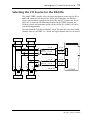
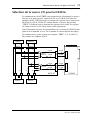
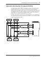
Selecting the I/O Source for the DS2416
The ADAT/THRU switches select the input and output sources for the IO-A
and IO-B connectors on the DS2416. In the ADAT position, the DS2416
receives and transmits signals via the ADAT IN and OUT connectors on the
AX16-AT, as shown in the following diagram. In the THRU position, the
DS2416 receives and transmits signals via the AX44s. IO-A and IO-B can be
switched independently.
The lines from the DS2416 are labeled “4 or 8” because they carry four audio
channel when set to THRU (i.e., AX44) and eight channels when set to ADAT.
A B
THRU-A
ADAT/
THRU-B
THRU-B
44
44
44
44
8888
AX44-BAX44-A
4 or 8
4 or 8
ADAT/
THRU-A
4 or 8
4 or 8
4 or 8
DS2416
AX16-AT
IO-AIO-B
IO-AIO-B
4 or 8
4 or 8
4 or 8
IN OUT IN OUT
ADAT-BADAT-A

12
Specifications
AX16-AT—Owner’s Manual
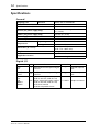
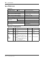
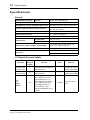
Specifications
General
Digital I/O
Sampling rate External
40.013 kHz to 50.880 kHz
ADAT/THRU switches
DS2416 I/O source selection
WORDCLOCK HALF/FULL switches
Wordclock source select
PCI-bus (for power supply only)
PCI Raw Variable Height Short Card
(5 V, 32-bit)
ISA-bus (for power supply only)
ISA card (5 V, 8-bit)
Power supply
+5 V (250 mA max)
Maximum power consumption
1.25 W
Temperature
Operating +10˚C to +35˚C
Storage –20˚C to +60˚C
Dimensions (H x L x D)
125.9 (ISA 127.7) x 188 x 21.6 mm
(4.95 x 7.4 x 0.85 inch)
Weight 120 g (4.2 oz)
Supplied accessories
20-pin cable x2
ISA-bus mounting bracket
Connection I/O Format Level Connector
A IN
B IN
I
ADAT MultiChannel Optical Digital
Interface
—
EIAJ fiber optical
jack
A OUT
B OUT
O
ADAT MultiChannel Optical Digital
Interface
—
EIAJ fiber optical
jack
IO-A
IO-B
THRU-A
THRU-B
I/O
4CH or 8CH digital audio inputs
(2CH or 4CH line, MSB first x2)
4CH or 8CH digital audio outputs
(2CH or 4CH line, MSB first x2)
32-bit max/channel
DS2416 compatible format
5 V CMOS 20-pin connector

Specifications 13
AX16-AT—Owner’s Manual
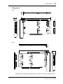
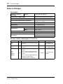
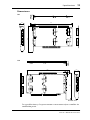
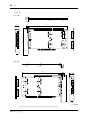
Dimensions
Specifications and external appearance are subject to change without notice.
21.6
3.1
188
125.9
A
A
A
[ THROUGH IO-A ]
THRU-A
B
B
THRU-B
B
[ THROUGH IO-B ]
[ THROUGH IO-B ]
B
B
B
[ THROUGH IO-A ]
A
A
A
IO-AIO-B
FULL
HALF
OFF
A
B
IN
IN
OUT
OUT
ADAT
THRU
3.1
188
127.7
[ THROUGH IO-A ]
THRU-ATHRU-B
[ THROUGH IO-B ]
[ THROUGH IO-B ]
B
B
B
B
B
B
A
A
A
A
A
A
[ THROUGH IO-A ]
IO-AIO-B
FULL
HALF
OFF
21.6
A
B
IN
IN
OUT
OUT
ADAT
THRU
Unit: mm
PCI
ISA

AX16-AT
CARTE D’EXPANSION AUDIO
Mode d’emploi
Français

2
AX16-AT—Mode d’emploi
Sommaire
Introduction . . . . . . . . . . . . . . . . . . . . . . . . . . . . . . . . . 4
Système requis . . . . . . . . . . . . . . . . . . . . . . . . . . . . . . . . . . . . 4
PCI ou ISA? . . . . . . . . . . . . . . . . . . . . . . . . . . . . . . . . . . . . . . . 4
Commandes et connexions . . . . . . . . . . . . . . . . . . . . . 5
A l’arrière . . . . . . . . . . . . . . . . . . . . . . . . . . . . . . . . . . . . . . . . 5
A l’intérieur . . . . . . . . . . . . . . . . . . . . . . . . . . . . . . . . . . . . . . . 6
Vue globale des connexions du système . . . . . . . . . . . 8
Installation de l’AX16-AT . . . . . . . . . . . . . . . . . . . . . . . 9
Adaptation de la fixation du bus ISA . . . . . . . . . . . . . . . . . 10
Sélection de la source I/O pour la DS2416 . . . . . . . . . . 11
Fiche technique . . . . . . . . . . . . . . . . . . . . . . . . . . . . . . . 12
Dimensions . . . . . . . . . . . . . . . . . . . . . . . . . . . . . . . . . . . . . 13

3
AX16-AT—Mode d’emploi
Remarques importantes
• Evitez de placer l’AX16-AT dans des endroits particulièrement chauds,
humides, poussiéreux ou en plein soleil.
• Gardez l’AX16-AT dans son sac antistatique jusqu’à ce que vous soyez
prêt à l’installer.
• Pour éviter tout dommage durant l’installation, tenez l’AX16-AT par les
bords ou la fixation.
• Si vous touchez accidentellement le circuit imprimé au bord de la carte,
enlevez toute empreinte digitale avec un mouchoir sec.
• Ne placez aucun objet sur l’AX16-AT et évitez de la déposer à un endroit
où des objets risquent d’être placés sur elle.
• Avant d’ouvrir le boîtier de l’ordinateur, mettez-le hors tension et
débranchez le cordon d’alimentation.
• Pour éviter tout endommagement par électricité statique, prenez en
main un objet métallique mis à la masse comme le boîtier d’alimentation
de votre ordinateur, par exemple, pour vous décharger de toute électricité
statique.
Contenu de l’emballage
• Carte d’expansion audio AX16-AT
• Câble de connexion à 20 broches DS2416 x2
• Fixation pour bus ISA
• Ce mode d’emploi
Marques commerciales
ADAT MultiChannel Optical Digital Interface est une marque commerciale et
ADAT ainsi qu’Alesis sont des marques déposées d’Alesis Corporation.
Yamaha est une marque déposée de Yamaha Corporation. Toutes les autres
marques appartiennent à leurs détenteurs respectifs et sont explicitement
reconnues.
Copyright
Ce mode d’emploi de l’AX16-AT ne peut être copié ou distribué sous quelque
forme ou par quelque moyen que ce soit sans l’autorisation écrite préalable de
Yamaha Corporation, Inc.
© 1998 Yamaha Corporation. Tous droits réservés.
Veuillez conserver ce manuel dans un lieu sûr pour toute réfé-
rence ultérieure!

4
Introduction
AX16-AT—Mode d’emploi
Introduction
Nous vous remercions d’avoir opté pour la carte d’expansion audio AX16-AT
de Yamaha. L’AX16-AT est une interface numérique de format ADAT pour la
carte de mélangeur numérique DS2416 de Yamaha. Avec ses deux entrées et
sorties ADAT MultiChannel Optical Digital, il est possible de transférer des
données audio numériques de format ADAT sur 16 canaux entre la DS2416 et
un enregistreur multipiste ADAT ou tout autre appareil ADAT tel qu’une con-
sole de mixage 02R, 03D ou 01V de Yamaha, dotée d’une carte ADAT I/O.
Système requis
• Ordinateur compatible avec la DS2416 disposant d’un bus PCI ou ISA
libre.
• Carte de mélangeur numérique Yamaha DS2416
• Logiciel audio compatible avec la DS2416
PCI ou ISA?
L’AX16-AT a été conçue pour une installation dans un connecteur PCI mais
peut également être placée dans un connecteur ISA. Il suffit d’échanger les
fixations et d’utiliser la fixation ISA prévue à cet effet. Comme les ordinateurs
Apple Macintosh compatibles avec la DS2416 ne comportent pas de bus ISA,
l’AX16-AT doit donc impérativement être installée dans un emplacement PCI
sur les Power Macs. Si vous vous servez d’un ordinateur Windows compatible
avec la DS2416, vous avez le choix entre un connecteur PCI ou ISA. Si tous les
bus PCI sont occupés, vous pouvez toujours installer l’AX16-AT pour autant
qu’il vous reste un bus ISA de libre.
Important: Si vous utilisez la DS2416 et l’AX16-AT sur un ordinateur tour-
nant sous Windows 95 ou 98, veillez à vous servir de la version V103 ou
ultérieure du pilote de la DS2416. La version la plus récente du pilote est
téléchargeable gratuitement à partir du site Yamaha Professional Audio.
<http://www.yamaha.co.jp/product/proaudio/homeenglish/>
La version V102, voire une version antérieure du pilote pour la DS2416, ne
permet pas l’utilisation du commutateur ADAT/THRU. Il n’empêche que vous
pouvez faire le nécessaire pour qu’il le reconnaisse en relançant le logiciel
audio compatible avec la DS2416.
Important: Lors de l’utilisation du mode Vari Pitch de la DS2416, la
fréquence d’échantillonnage ainsi que les données Wordclock changent
aussi. Dans ce cas, certains appareils connectés à l’AX16-AT (en tant
qu’esclaves Wordclock) risquent de ne plus pouvoir être synchronisés. Cer-
tains réglages (produisant des fréquences d’échantillonnage reconnues) peu-
vent cependant donner le résultat escompté.

Commandes et connexions
5
AX16-AT—Mode d’emploi
Commandes et connexions
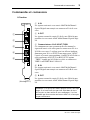
A l’arrière
A
A IN
Les signaux arrivant à cette entrée ADAT MultiChannel
Optical Digital sont envoyés au connecteur IO-A de cette
carte.
B
A OUT
Les signaux venant des sorties IO de la carte DS2416 sont
produits via cette sortie ADAT MultiChannel Optical Digi-
tal.
C
Commutateurs
A & B ADAT/THRU
Ces commutateurs vous permettent de sélectionner les
signaux d’entrée et de sortie pour les connecteurs IO-A et
IO-B de cette carte. Ce réglage peut être effectué indépen-
damment pour IO-A et IO-B. Si vous optez pour “ADAT”,
l’entrée et la sortie correspondante (A ou B) de la DS2416 est
reliée aux bornes A IN/OUT ou B IN/OUT. L’option
“THRU” signifie que la DS2416 est reliée au connecteur
THRU A ou THRU B de l’AX16-AT.
D
B IN
Les signaux arrivant à cette entrée ADAT MultiChannel
Optical Digital sont envoyés au connecteur IO-B de cette
carte.
E
B OUT
Les signaux venant des sorties IO de la carte DS2416 sont
produits via cette sortie ADAT MultiChannel Optical Digi-
tal.
Remarque: Si les prises des câbles optiques utilisés sont trop
larges en n’entrent dès lors pas tout à fait dans la fente
d’extension en face arrière de votre ordinateur, il est fort
probable que la connexion aux bornes ADAT ne se fasse pas
ou pas entièrement.
1
2
3
4
5
A
B
IN
IN
OUT
(Montage PCI)
OUT
ADAT
THRU

6
Commandes et connexions
AX16-AT—Mode d’emploi
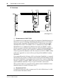
A l’intérieur
A
Commutateurs HALF/FULL
Ces commutateurs permettent de régler des paramètres Wordclock lorsque la
DS2416 est asservie à l’horloge Wordclock de l’AX16-AT. IO-A et IO-B peu-
vent être réglés séparément. En position “FULL”, la DS2416 tire son signal
Wordclock de la source sélectionnée avec les commutateurs ADAT/THRU.
Normalement, ces commutateurs doivent être réglés sur “HALF” (réglage
d’usine) car, ainsi, la DS2416 utilise toujours le signal Wordclock présent à la
borne ADAT IN, quel que soit le réglage des commutateurs ADAT/THRU.
Cela vous permet de commuter entre des connecteurs ADAT et THRU (AX44
ou d’autres appareils) car vous ne devez pas chaque fois modifier le réglage
Wordclo ck.
Si un appareil branché à la borne A IN sert de maître Wordclock, cet appareil
doit être mis sous tension et configuré correctement pour fonctionner en tant
que maître Wordclock. Si, pour une raison ou une autre, la source Wordclock
externe est perdue, les bornes THRU sont passées en revue à la recherche d’un
signal Wordclock utilisable. S’il n’y en a pas, la DS2416 est désactivée.
(Pour pouvoir utiliser un appareil externe comme maître Wordclock, il faut
impérativement le brancher à la borne A IN.)
B
Connecteur IO-A
Ce connecteur peut être relié au connecteur IO-A de la DS2416 avec le câble
de connexion à 20 broches fourni.
45231
A
A
A
[ THROUGH IO-A ]
THRU-A
B
B
THRU-B
B
[ THROUGH IO-B ]
[ THROUGH IO-B ]
B
B
B
[ THROUGH IO-A ]
A
A
A
IO-AIO-B
FULL
HALF
OFF
(Montage PCI)

Commandes et connexions
7
AX16-AT—Mode d’emploi
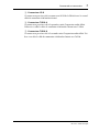
C
Connecteur IO-B
Ce connecteur peut être relié au connecteur IO-B de la DS2416 avec le second
câble de connexion à 20 broches fourni.
D
Connecteur THRU-A
Ce connecteur peut être relié à la première unité d’expansion audio AX44.
Utilisez à cet effet le câble de connexion à 20 broches fourni avec l’AX44.
E
Connecteur THRU-B
Ce connecteur peut être relié à la seconde unité d’expansion audio AX44. Uti-
lisez à cet effet le câble de connexion à 20 broches fourni avec l’AX44.
Strona jest ładowana ...
Strona jest ładowana ...
Strona jest ładowana ...
Strona jest ładowana ...
Strona jest ładowana ...
Strona jest ładowana ...
Strona jest ładowana ...
Strona jest ładowana ...
Strona jest ładowana ...
Strona jest ładowana ...
Strona jest ładowana ...
Strona jest ładowana ...
Strona jest ładowana ...
Strona jest ładowana ...
Strona jest ładowana ...
Strona jest ładowana ...
Strona jest ładowana ...
Strona jest ładowana ...
Strona jest ładowana ...
Strona jest ładowana ...
Strona jest ładowana ...
Strona jest ładowana ...
Strona jest ładowana ...
Strona jest ładowana ...
Strona jest ładowana ...
Strona jest ładowana ...
Strona jest ładowana ...
Strona jest ładowana ...
Strona jest ładowana ...
Strona jest ładowana ...
Strona jest ładowana ...
Strona jest ładowana ...
Strona jest ładowana ...
Strona jest ładowana ...
Strona jest ładowana ...
Strona jest ładowana ...
Strona jest ładowana ...
Strona jest ładowana ...
Strona jest ładowana ...
Strona jest ładowana ...
Strona jest ładowana ...
Strona jest ładowana ...
Strona jest ładowana ...
Strona jest ładowana ...
Strona jest ładowana ...
-
 1
1
-
 2
2
-
 3
3
-
 4
4
-
 5
5
-
 6
6
-
 7
7
-
 8
8
-
 9
9
-
 10
10
-
 11
11
-
 12
12
-
 13
13
-
 14
14
-
 15
15
-
 16
16
-
 17
17
-
 18
18
-
 19
19
-
 20
20
-
 21
21
-
 22
22
-
 23
23
-
 24
24
-
 25
25
-
 26
26
-
 27
27
-
 28
28
-
 29
29
-
 30
30
-
 31
31
-
 32
32
-
 33
33
-
 34
34
-
 35
35
-
 36
36
-
 37
37
-
 38
38
-
 39
39
-
 40
40
-
 41
41
-
 42
42
-
 43
43
-
 44
44
-
 45
45
-
 46
46
-
 47
47
-
 48
48
-
 49
49
-
 50
50
-
 51
51
-
 52
52
-
 53
53
-
 54
54
-
 55
55
-
 56
56
-
 57
57
-
 58
58
-
 59
59
-
 60
60
-
 61
61
-
 62
62
-
 63
63
-
 64
64
-
 65
65


Yamaha AX16 Instrukcja obsługi
- Kategoria
- Miksery audio
- Typ
- Instrukcja obsługi
- Ten podręcznik jest również odpowiedni dla
w innych językach
- čeština: Yamaha AX16 Návod k obsluze
- español: Yamaha AX16 El manual del propietario
- italiano: Yamaha AX16 Manuale del proprietario
- Deutsch: Yamaha AX16 Bedienungsanleitung
- svenska: Yamaha AX16 Bruksanvisning
- português: Yamaha AX16 Manual do proprietário
- français: Yamaha AX16 Le manuel du propriétaire
- 日本語: Yamaha AX16 取扱説明書
- Türkçe: Yamaha AX16 El kitabı
- English: Yamaha AX16 Owner's manual
- dansk: Yamaha AX16 Brugervejledning
- русский: Yamaha AX16 Инструкция по применению
- Nederlands: Yamaha AX16 de handleiding
- română: Yamaha AX16 Manualul proprietarului
Powiązane dokumenty
-
Yamaha DS2416 Instrukcja obsługi
-
-
-
-
-
-
-
-
-