
Dell PowerEdge
C6220 II
Getting Started
With Your System
Začínáme se systémem
Mise en route du système
Handbuch zum Einstieg
mit dem System
Τα πρώτα βήματα με το σύστημά σας
Instrukcja uruchomienia systemu
Руководство по началу
работы с сервером
Pasos iniciales para su sistema
Sisteminizi Kullanmaya Başlarken


Dell PowerEdge
C6220 II
Getting Started
With Your System

Notes, Cautions, and Warnings
NOTE:
A NOTE indicates important information that helps you make better use of
your computer.
CAUTION: A CAUTION indicates potential damage to hardware or loss of
data if instructions are not followed.
WARNING: A WARNING indicates a potential for property damage,
personal injury, or death.
______________
Information in this document is subject to change without notice.
© 2013 Dell Inc. All rights reserved.
Reproduction of these materials in any manner whatsoever without the written permission
of Dell Inc. is strictly forbidden.
Trademarks used in this text: Dell™, the DELL logo, and PowerEdge™ are trademarks of
Dell Inc. Intel® and Intel® Xeon® are registered trademarks of Intel Corporation in the
U.S. and other countries. Red Hat Enterprise Linux® and Enterprise Linux® are
registered trademarks of Red Hat, Inc. in the United States and/or other countries.
Novell® is a registered trademark and SUSE™ is a trademark of Novell Inc. in the United
States and other countries. Citrix® and XenServer® are either registered trademarks or
trademarks of Citrix Systems, Inc. in the United States and/or other countries. VMware®
is a registered trademarks or trademarks of VMWare, Inc. in the United States or other
countries.
Other trademarks and trade names may be used in this publication to refer to either the
entities claiming the marks and names or their products. Dell Inc. disclaims any
proprietary interest in trademarks and trade names other than its own.
Regulatory Model B08S
May 2013 P/N MYF2N Rev. A00

Getting Started With Your System | 3
CAUTION: Restricted Access Location
This server is intended for installation only in restricted access locations as
defined in Cl. 1.2.7.3 of IEC 60950-1: 2001 where both these conditions apply:
•
Access can only be gained by service persons or by users
who have been
instructed about the reasons for the restrictions applied to the location and
about any precautions that shall be taken.
•
Access is through the use of a tool or lock and key, or other means of
security, and is controlled by the authority responsible for the location.
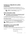
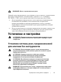
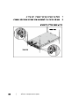
Installation and Configuration
WARNING: Before performing the following procedure, review and follow the
safety instructions that came with the system.
Installing the Tool-Less Rail Solution
WARNING: Whenever you need to lift the system, get others to assist you.
To avoid injury, do not attempt to lift the system by yourself.
WARNING: The system is not fixed to the rack or mounted on the rails. To
avoid personal injury or damage to the system, you must adequately
support the system during installation and removal.
WARNING: To avoid a potential electrical shock hazard, a third wire safety
grounding conductor is necessary for the rack installation. The rack
equipment must provide sufficient airflow to the system to maintain proper
cooling.
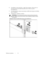
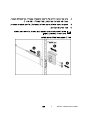
CAUTION: When installing rails in a square-hole rack it is important to
ensure that the square peg slides through the square holes.

Getting Started With Your System | 4
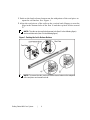
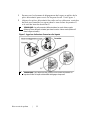
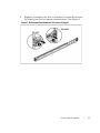
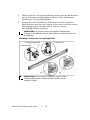
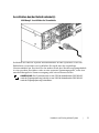
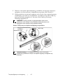
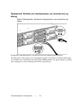
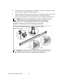
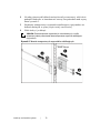
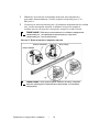
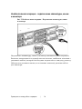
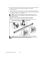
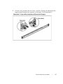
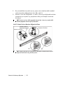
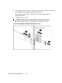
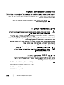
1
Push on the latch release buttons on the midpoints of the end piece to
open the rail latches. See Figure 1.
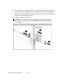
2
Align the end pieces of the rails on the vertical rack flanges to seat the
pegs in the bottom hole of the first U and the top hole of the second
U.
NOTE:
The rails can be used in both square-hole (item 1 in the following figure)
and round-hole racks (item 2 in the following figure).
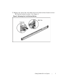
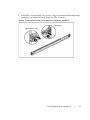
Figure 1. Pushing the Latch Release Buttons
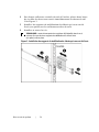
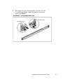
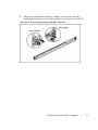
NOTE:
To remove the rails, push on the latch release button on the midpoints
of the end piece and unseat each rail.


Getting Started With Your System | 6
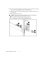
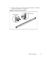
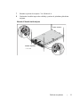
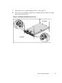
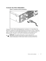
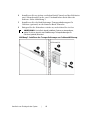
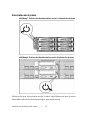
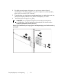
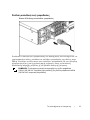
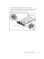
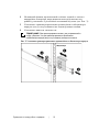
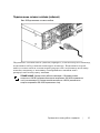
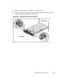
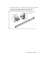
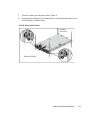
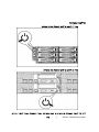
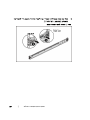
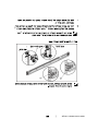
4
On each vertical rack flange on the back, put two screw bases into the
two square holes right above the rail. See Figure 3.
5
Install the chassis stabilizer shipping brackets (optional) on the back
rack flanges.
6
Install and tighten the screws.
NOTE:
To transport systems already installed in the rack, ensure that the two
chassis stabilizer shipping brackets (optional) are in place.
Figure 3. Installing the Chassis Stabilizer Shipping Brackets


Getting Started With Your System | 8
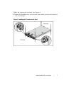
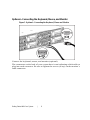
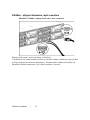
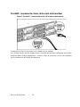
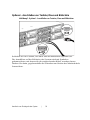
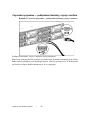
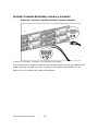
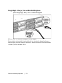
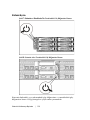
Optional—Connecting the Keyboard, Mouse, and Monitor
Figure 5. Optional—Connecting the Keyboard, Mouse and Monitor
Connect the keyboard, mouse, and monitor (optional).
The connectors on the back of your system have icons indicating which cable to
plug into each connector. Be sure to tighten the screws (if any) on the monitor’s
cable connector.

Getting Started With Your System | 9
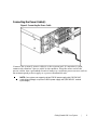
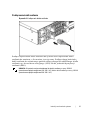
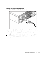
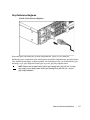
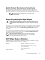
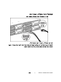
Connecting the Power Cable(s)
Figure 6. Connecting the Power Cable
Connect the system’s power cable(s) to the system and, if a monitor is used,
connect the monitor’s power cable to the monitor. Plug the other end of the
power cables into a grounded electrical outlet or a separate power source such as
an uninterrupted power supply or a power distribution unit.
NOTE:
Your system can support up to two 1200 W power supply units (100-240 VAC
nominal input voltage) or up to two 1400 W power supply units (200-240 VAC nominal
input voltage).

Getting Started With Your System | 10
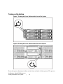
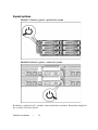
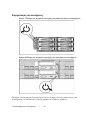
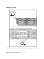
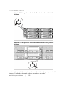
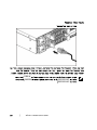
Turning on the System
Figure 7. Pressing the Power Button on the Front of the System
Figure 8. Pressing the Power Button on the Back of the System
Press the power button(s) either on the front or back of the system. The power
indicators should light green.

Getting Started With Your System | 11
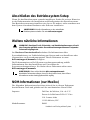
Complete the Operating System Setup
To install an operating system for the first time, see the installation and
configuration documentation for your operating system. Be sure the operating
system is installed before installing hardware or software not purchased with the
system.
NOTE:
See dell.com/ossupport for the latest information on supported
operating systems.
Other Information You May Need
WARNING: See the safety and regulatory information that shipped with your
system. Warranty information may be included within this document or as a
separate document.
The Hardware Owner’s Manual provides information about system features and
describes how to troubleshoot the system and install or replace system
components. This document is available at
dell.com/support/manuals
.
Dell systems management application documentation provides information
about installing and using the systems management software. This document is
available online at
dell.com/support/manuals
.
NOTE:
Always check for updates on
dell.com/support/manuals
and read the
updates first because they often supersede information in other documents.
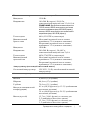
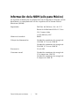
NOM Information (Mexico Only)
The following information is provided on the device described in this document
in compliance with the requirements of the official Mexican standards (NOM):
Importer Dell Inc. de México, S.A. de C.V.
Paseo de la Reforma 2620-11° Piso
Col. Lomas Atlas
11950 México, D.F.
Model number B08S

Getting Started With Your System | 12
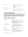
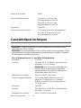
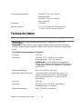
Supply voltage 100-240 V AC with 1200 W Power
Supply Unit
200-240 V AC with 1400 W Power
Supply Unit
Frequency 50/60 Hz
Current consumption
12-8 Amps with 1200 W Power Supply
Unit
9 Amps with 1400 W Power Supply
Unit
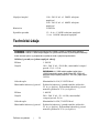
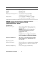
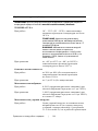
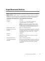
Technical Specifications
Power
NOTE:
The system doesn’t support a mixed
installation of 1200 W and 1400 W power supply
units.
NOTE:
Both the 1200 W and 1400 W PSUs are hot swappable, and they can support hot swap in
any condition if the system has the power throttling feature.
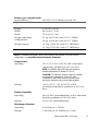
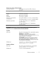
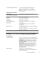
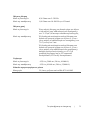
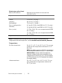
AC power supply (per power supply)
Wattage
1200 W
Voltage 100-240 VAC, 50/60 Hz, maximum input
current: 12.0-8.0 Amps
NOTE:
For 1200 W power supply, output 1200 W is for
high line (input 200-240 VAC), output 1023 W is for low
line (input 100-120 VAC).
Heat dissipation
4016.251 BTU/hr maximum
Maximum inrush current Initial In-rush Current cannot exceed 55
Amps (peak). Secondary In-rush Current
cannot exceed 35 Amps (peak).
Wattage
1400 W
Voltage 200-240 VAC, 50-60 Hz, maximum input
current: 9.0 Amps
Heat dissipation
6024.376 BTU/hr maximum.
Maximum in-rush current Initial In-rush Current cannot exceed 55
Amps (peak). Secondary In-rush Current
cannot exceed 25 Amps (peak).

Getting Started With Your System | 13
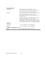
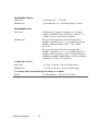
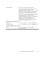
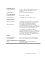
Battery (per system board)
System battery
CR 2032 3.0-V lithium ion coin cell
Physical
Height
8.68 cm (3.42 in)
Width
44.8 cm (17.6 in)
Depth
79.0 cm (31.1 in)
Weight (maximum
configuration)
41 kg (90.38 lb) (with 12*3.5” HDD)
39 kg (86.00 lb) (with 24*2.
5” HDD)
Weight (empty) 15.7 kg (34.61 lb) (with 2.5” HDD bay)
15.1 kg (33.29 lb) (with 3.5” HDD bay)
Environmental
NOTE:
For additional information about environmental measurements for specific system
configurations, see
www.dell.com/environmental_datasheets
.
Temperature
Operating 10° to 35°C (50° to 95°F) with a maximum
temperature gradation of 10°C per hour
NOTE:
For altitudes above 2950 feet, the maximum
operating temperature is derated 1°F/550 ft.
CAUTION:
The maximum number of memory modules
and hard drives supported on 1U and 2U node
configurations, with 130W (4 and 8 core) and 135W
processors, depends on the power supply installed.
Storage –40° to 65°C (–40° to 149°F) with a
maximum temperature gradation of 20°C per
hour
Relative humidity
Operating 20% to 80% (noncondensing) with a maximum
humidity gradation of 10% per hour
Storage
5% to 95% (noncondensing)
Maximum vibration
Operating
0.26 Grms at 5–350 Hz
Storage 1.88 Grms at 10–500 Hz for 15 min

Getting Started With Your System | 14
Maximum shock
Operating One shock pulse in the positive z axis
(one pulse on each side of the system) of 31 G
for 2.6 ms in the operational orientation
Storage Six consecutively executed shock pulses in the
positive and negative x, y, and z axes
(one pulse on each side of the system) of 71 G
for up to 2 ms;
Six consecutively executed shock pulses in the
positive and negative x, y, and z axes
(one pulse on each side of the system) of 27 G
faired square wave pulse with velocity change
at 235 inches/second (597 centimeters/second)
Altitude
Operating
-15.2 to 3,048 m (-50 to 10,000 ft.)
Storage
-15.2 to 10,668 m (-50 to 35,000 ft.)
Airborne Contaminant Level
Class
G1 as defined by ISA-S71.04-1985

Dell PowerEdge
C6220 II
Začínáme
se systémem

Poznámky a upozornění
POZNÁMKA:
POZNÁMKA označuje důležité informace, které vám pomohou počítač
lépe využít.
UPOZORNĚNÍ: UPOZORNĚNÍ označuje možné poškození hardwaru nebo
ztrátu dat v případě nedodržení pokynů.
VAROVÁNÍ: VAROVÁNÍ označuje možné poškození majetku, riziko
poranění nebo smrti.
______________
Informace uvedené v tomto dokumentu mohou být bez upozornění měněny.
© 2013 Dell Inc. Všechna práva vyhrazena.
Kopírování těchto materiálů jakýmkoli způsobem bez písemného svolení společnosti
Dell Inc. je přísně zakázáno.
Ochranné známky použité v tomto textu: Dell™, logo DELL a PowerEdge™ jsou
ochranné známky společnosti Dell Inc. Intel® a Intel® Xeon® jsou registrované ochranné
známky společnosti Intel Corporation v USA a v jiných zemích. Red Hat Enterprise
Linux® a Enterprise Linux® jsou registrované ochranné známky společnosti Red Hat, Inc.
ve Spojených státech anebo v jiných zemích. Novell® je registrovaná ochranná známka a
SUSE™ je ochranná známka společnosti Novell Inc. ve Spojených státech a v jiných
zemích. Citrix® a XenServer® jsou buď registrované ochranné známky, nebo ochranné
známky společnosti Citrix Systems, Inc. ve Spojených státech anebo v jiných zemích.
VMware® je registrovaná ochranná známka nebo ochranná známka společnosti VMWare,
Inc. ve Spojených státech nebo v jiných zemích.
V této publikaci mohou být použity další ochranné známky a obchodní názvy označující
buď subjekty vlastnící tyto známky a názvy, nebo jejich produkty. Společnost Dell Inc.
se zříká veškerých vlastnických nároků na ochranné známky a obchodní názvy jiné než
své vlastní.
Směrnicový model B08S
Květen 2013 Č. dílu MYF2N Rev. A00

Začínáme se systémem | 17
UPOZORNĚNÍ: Umístění s omezeným přístupem
Tento server je určen k montáži pouze na místa s omezeným přístupem, jak jsou
definována v čl. 1.2.7.3 normy IEC 60950-1: 2001, kde platí obě následující
podmínky:
•
Přístup mohou získat pouze servisní pracovníci či uživatelé, kteří byli
poučeni o důvodech omezení platných pro toto místo a o veškerých
opatřeních, která je třeba dodržovat.
•
Přístup je zajišťován prostřednictvím nástroje nebo zámku a klíče nebo
prostřednictvím jiného typu zabezpečení a je řízen osobou zodpovědnou
za toto umístění.
Montáž a konfigurace
VAROVÁNÍ: Před provedením následujícího postupu si prostudujte
bezpečnostní pokyny dodané se systémem a řiďte se jimi.
Montáž kolejniček bez použití nářadí
VAROVÁNÍ: Potřebujete-li systém zvednout, požádejte o pomoc další
osoby. Nebudete-li systém zvedat sami, předejdete možnému zranění.
VAROVÁNÍ: Systém není upevněn ke stojanu ani namontován na
kolejničkách. Chcete-li předejít zranění osob nebo poškození systému,
musíte systém během montáže a vyjímání dostatečně stabilizovat.
VAROVÁNÍ: Chcete-li předejít možnému nebezpečí úrazu elektrickým
proudem, je třeba při montáži do stojanu použít třetí bezpečnostní zemnicí
vodič. Stojanové vybavení musí systému poskytovat dostatečné proudění
vzduchu, a zajišťovat tak správné chlazení.
UPOZORNĚNÍ: Při montáži kolejniček do stojanu se čtvercovými otvory je
důležité zajistit, aby byl čtyřboký kolík skrz čtvercové otvory správně
zasunut.

Začínáme se systémem | 18
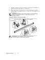
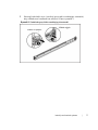
1
Západky kolejniček otevřete stisknutím uvolňovacích knoflíků ve
středu koncovek kolejniček. Viz Obrázek 1.
2
Zarovnejte koncovky kolejniček se svislými přírubami stojanu a
usaďte kolíky do spodního otvoru ve výšce 1U a do horního otvoru
ve výšce 2U.
POZNÁMKA:
Kolejničky je možno použít ve stojanech se čtvercovými otvory
(položka 1 na následujícím obrázku) i s kulatými otvory (položka 2 na
následujícím obrázku).
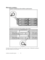
Obrázek 1. Stisknutí uvolňovacích knoflíků
POZNÁMKA:
Chcete-li kolejničky vyjmout, uvolněte je stisknutím
uvolňovacího knoflíku ve středu koncovky kolejničky.
Pohled zepředu
Uvolňovací knoflík
Pohled zezadu
Strona się ładuje...
Strona się ładuje...
Strona się ładuje...
Strona się ładuje...
Strona się ładuje...
Strona się ładuje...
Strona się ładuje...
Strona się ładuje...
Strona się ładuje...
Strona się ładuje...
Strona się ładuje...
Strona się ładuje...
Strona się ładuje...
Strona się ładuje...
Strona się ładuje...
Strona się ładuje...
Strona się ładuje...
Strona się ładuje...
Strona się ładuje...
Strona się ładuje...
Strona się ładuje...
Strona się ładuje...
Strona się ładuje...
Strona się ładuje...
Strona się ładuje...
Strona się ładuje...
Strona się ładuje...
Strona się ładuje...
Strona się ładuje...
Strona się ładuje...
Strona się ładuje...
Strona się ładuje...
Strona się ładuje...
Strona się ładuje...
Strona się ładuje...
Strona się ładuje...
Strona się ładuje...
Strona się ładuje...
Strona się ładuje...
Strona się ładuje...
Strona się ładuje...
Strona się ładuje...
Strona się ładuje...
Strona się ładuje...
Strona się ładuje...
Strona się ładuje...
Strona się ładuje...
Strona się ładuje...
Strona się ładuje...
Strona się ładuje...
Strona się ładuje...
Strona się ładuje...
Strona się ładuje...
Strona się ładuje...
Strona się ładuje...
Strona się ładuje...
Strona się ładuje...
Strona się ładuje...
Strona się ładuje...
Strona się ładuje...
Strona się ładuje...
Strona się ładuje...
Strona się ładuje...
Strona się ładuje...
Strona się ładuje...
Strona się ładuje...
Strona się ładuje...
Strona się ładuje...
Strona się ładuje...
Strona się ładuje...
Strona się ładuje...
Strona się ładuje...
Strona się ładuje...
Strona się ładuje...
Strona się ładuje...
Strona się ładuje...
Strona się ładuje...
Strona się ładuje...
Strona się ładuje...
Strona się ładuje...
Strona się ładuje...
Strona się ładuje...
Strona się ładuje...
Strona się ładuje...
Strona się ładuje...
Strona się ładuje...
Strona się ładuje...
Strona się ładuje...
Strona się ładuje...
Strona się ładuje...
Strona się ładuje...
Strona się ładuje...
Strona się ładuje...
Strona się ładuje...
Strona się ładuje...
Strona się ładuje...
Strona się ładuje...
Strona się ładuje...
Strona się ładuje...
Strona się ładuje...
Strona się ładuje...
Strona się ładuje...
Strona się ładuje...
Strona się ładuje...
Strona się ładuje...
Strona się ładuje...
Strona się ładuje...
Strona się ładuje...
Strona się ładuje...
Strona się ładuje...
Strona się ładuje...
Strona się ładuje...
Strona się ładuje...
Strona się ładuje...
Strona się ładuje...
Strona się ładuje...
Strona się ładuje...
Strona się ładuje...
Strona się ładuje...
Strona się ładuje...
Strona się ładuje...
Strona się ładuje...
Strona się ładuje...
Strona się ładuje...
Strona się ładuje...
Strona się ładuje...
Strona się ładuje...
Strona się ładuje...
Strona się ładuje...
Strona się ładuje...
-
 1
1
-
 2
2
-
 3
3
-
 4
4
-
 5
5
-
 6
6
-
 7
7
-
 8
8
-
 9
9
-
 10
10
-
 11
11
-
 12
12
-
 13
13
-
 14
14
-
 15
15
-
 16
16
-
 17
17
-
 18
18
-
 19
19
-
 20
20
-
 21
21
-
 22
22
-
 23
23
-
 24
24
-
 25
25
-
 26
26
-
 27
27
-
 28
28
-
 29
29
-
 30
30
-
 31
31
-
 32
32
-
 33
33
-
 34
34
-
 35
35
-
 36
36
-
 37
37
-
 38
38
-
 39
39
-
 40
40
-
 41
41
-
 42
42
-
 43
43
-
 44
44
-
 45
45
-
 46
46
-
 47
47
-
 48
48
-
 49
49
-
 50
50
-
 51
51
-
 52
52
-
 53
53
-
 54
54
-
 55
55
-
 56
56
-
 57
57
-
 58
58
-
 59
59
-
 60
60
-
 61
61
-
 62
62
-
 63
63
-
 64
64
-
 65
65
-
 66
66
-
 67
67
-
 68
68
-
 69
69
-
 70
70
-
 71
71
-
 72
72
-
 73
73
-
 74
74
-
 75
75
-
 76
76
-
 77
77
-
 78
78
-
 79
79
-
 80
80
-
 81
81
-
 82
82
-
 83
83
-
 84
84
-
 85
85
-
 86
86
-
 87
87
-
 88
88
-
 89
89
-
 90
90
-
 91
91
-
 92
92
-
 93
93
-
 94
94
-
 95
95
-
 96
96
-
 97
97
-
 98
98
-
 99
99
-
 100
100
-
 101
101
-
 102
102
-
 103
103
-
 104
104
-
 105
105
-
 106
106
-
 107
107
-
 108
108
-
 109
109
-
 110
110
-
 111
111
-
 112
112
-
 113
113
-
 114
114
-
 115
115
-
 116
116
-
 117
117
-
 118
118
-
 119
119
-
 120
120
-
 121
121
-
 122
122
-
 123
123
-
 124
124
-
 125
125
-
 126
126
-
 127
127
-
 128
128
-
 129
129
-
 130
130
-
 131
131
-
 132
132
-
 133
133
-
 134
134
-
 135
135
-
 136
136
-
 137
137
-
 138
138
-
 139
139
-
 140
140
-
 141
141
-
 142
142
-
 143
143
-
 144
144
-
 145
145
-
 146
146
-
 147
147
-
 148
148
-
 149
149
-
 150
150


w innych językach
Powiązane artykuły
-
Dell PowerEdge C6220 Instrukcja obsługi
-
-
-
-
-