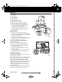
Whirlpool AKR 957 IX WP Program Chart
- Kategoria
- Okapy kuchenne
- Typ
- Program Chart

5019 318 33097
AKR 957
KARTA INSTALACYJNA
Minimalna odległość od palników: 50 cm (palniki elektryczne), 75 cm
(palniki gazowe, olejowe lub węglowe). Podczas montażu należy
przestrzegać kolejności numeracji (
1
Ö
2
Ö
3
Ö
.....). Nie podłączać
urządzenia do zasilania, zanim nie zostanie zakończony całkowicie jego
montaż. Uwaga! Przewód wylotowy oraz kolanka mocujące (15) nie
znajdują się na wyposażeniu i należy je dokupić.
POPIS INSTALACE
Minimální vzdálenost od sporáků: 50 cm (elektrické sporáky), 75 cm
(sporáky na plyn, naftu nebo uhlí). Při montáži sledujte číslování
(
1
Ö
2
Ö
3
Ö
.....). Spotřebič připojte k elektrické síti až po úplném dokončení
instalace. Upozornění! Nasávací trubka a upevňovací pásky (15) nejsou
součástí vybavení a musíte je zakoupit.
INŠTALAČNÁ SCHÉMA
Minimálna vzdialenost' od sporáka: 50 cm (elektrické sporáky), 75 cm
(plynové sporáky, sporáky na naftu alebo uhlie). Pri montáži postupujte
podľa číslic (
1
Ö
2
Ö
3
Ö
.....). Spotrebič nezapájajte do siete, kým nie je
inštalácia úplne ukončená. Upozornenie! Rúra na odvádzanie dymov a
upevňovacie svorky (15) sa nedodávajú, musíte ich kúpit' samostatne.
ÜZEMBE HELYEZÉSI ÚTMUTATÓ
A tűzhelytől való minimális távolság: 50 cm (elektromos tűzhely), 75 cm
(gáz-, olaj- vagy széntüzelésű tűzhely). A felszereléshez kövesse a
számozást (
1
Ö
2
Ö
3
Ö
.....). A készüléket csak akkor szabad áram alá
helyezni, ha a beüzemelés már megtörtént. Figyelem! Az elvezető cső és
a rögzítőpántok (15) nem tartozékok, így azokat külön meg kell vásárolni.
СХЕМА УСТАНОВКИ
lМинимальное расстояние до конфорок: 50 см (электрические
конфорки), 75 см (газовые, керосиновые или угольные).
Последовательность действий при монтаже должна
соответствовать нумерации (
1
Ö
2
Ö
3
Ö
.....). Не подключайте
прибор к сети до тех пор, пока его установка не будет полностью
закончена. Внимание! Выпускная труба и крепежные зажимы (15)
не входят в комплект поставки и приобретаются отдельно.
КАРТА ЗА ИНСТАЛИРАНЕ
Минимално разстояние от печки: 50 см (електрически печки),
75 см (печки с газ, нафта или въглища). За монтаж следвайте
номерацията (
1
Ö
2
Ö
3
Ö
.....). Не включвайте захранването на уреда,
докато инсталирането не е завършено докрай. Внимание! Тръбата
за отвеждане не е предоставена и трябва да се закупи отделно.
FIȘA DE INSTALARE
Distanţa minimă de la arzătoare: 50 cm (arzătoare electrice), 75 cm (arzătoare
pe bază de gaze, petrol sau cărbune). Pentru montaj urmaţi numerotarea
(
1
Ö
2
Ö
3
Ö
.....). Nu branșaţi aparatul la curent până când nu terminaţi definitiv
operaţia de instalare. Atenţie! Tubul de evacuare și manșoanele de fixare (15)
nu fac parte din dotare și trebuie să fie cumpărate separat.
INSTALLATION SHEET
Minimum height above cooker: 50 cm (electric cookers), 75 cm (gas, gas oil or coal
cookers). To install, follow points (1
Ö
2
Ö
3
Ö
.....). Do not connect the appliance to
the electrical power supply until installation is completed. Warning! The exhaust pipe
and clamps (15) are not supplied and must be bought separately.
PL
CZ
SK
H
RUS
BG
RO
GB
31833097.fm Page 1 Tuesday, November 11, 2003 12:45 PM

5019 318 33097
AKR 957
=
=
X
G
17b
17b
4-13
4-13
1
2
3
11
11
12
15
17a
17a
6
5
16
B
G
H
8
8
18
F
9
10
14
7
9
1
0
1
4
7
5
6
4 x 4x8
4 x 3,5x9,5
2 x
2,9x6,5
31833097.fm Page 2 Tuesday, November 11, 2003 12:45 PM

5019 318 33097
AKR 957
PL SK H RUS
CZ
BG RO GB
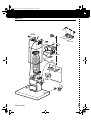
INSTALLATION - ASSEMBLY INSTRUCTIONS
Preliminary information for installing the hood
Disconnect the power supply at the domestic main switch before carrying out electrical connections.
Remove the grease filter/s.
Pre-assemble the three parts of the flue support bracket with 4 screws. The width
X
of the bracket
G
must be
identical to the internal width of the telescopic flue.
1.
Using a pencil, draw the centre line on the wall up to the ceiling to facilitate installation operations.
2.
Attach the hole diagram to the wall: the vertical centre line printed on the hole diagram must match the
centre line drawn on the wall, and the lower edge of the hole diagram must match the lower edge of the
hood: remember that with installation completed the bottom of the hood must be at least 50 cm above
the cooktop in case of electric cookers and 75 cm in case of gas or mixed cookers.
3.
Place the support bracket on the hole diagram so that it matches the dashed rectangle, mark the two
external holes and drill, remove the hole diagram, insert 2 wall plugs and fix the hood support bracket
with two 5x45 mm screws.
4.
Hook the hood to the bracket.
5.
Adjust the distance between the hood and the wall.
6.
Adjust the hood horizontally.
7.
From the inside of the extraction unit, mark the holes for fixing the hood.
8.
Remove the hood from the bracket.
9.
Drill on the marks (Ø 8 mm - see step 10)
10.
Insert 2 wall plugs.
11.
Fit the flue support bracket
G
to the wall and against the ceiling, use the support bracket as hole diagram
(the small slot on the support must match the line drawn on the wall - step 4) and mark 2 holes with the
pencil, drill the holes (Ø 8 mm), and finally insert 2 plugs.
12.
Fix the flue support bracket to the wall with two 5x45 mm screws.
13.
Hook the hood to the bottom bracket.
14.
Fix the hood to the wall with two 5x45 mm screws (ABSOLUTELY NECESSARY).
15.
Connect an exhaust pipe (pipe and clamps are not supplied and must be bought separately) to the collar
B
located above the extraction motor unit.
For extractor operation, connect the other end of the exhaust pipe to the home discharge device. For filter
operation, fix the deflector
F
to the flue support bracket
G
and connect the other end of the exhaust pipe
to the deflector collar
F
. Once the steam and fumes have been filtered by the carbon filter (not provided,
to be ordered separately) they are conveyed back to the kitchen through grid
H
.
16.
Carry out the electrical connection.
17.
Apply the flues and fix them with 2 screws (
20a
) to the flue support
G
(
20b
).
18.
Slide the bottom section of the flue in the special seat above the hood to completely cover the extraction
unit.
Refit the grease filter/s and check for correct hood operation.
31833097.fm Page 24 Tuesday, November 11, 2003 12:45 PM

5019 318 33097
AKR 957
PL SK H RUS
CZ
BG RO GB
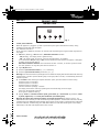
CONTROL PANEL
Control panel calibration
When the appliance is plugged in (or after a power failure) the system calibrates the buttons; during
calibration two blinking dots will appear.
The calibration lasts for 15''.
At the end of the calibration procedure, the two dots will stop blinking and only the bottom right dot will
stay alight.
1.
ON
button (Stand by) /
OFF
extraction /
Resetfilter saturation
indicator:
-
ON
(Stand by) - the display shows a lighted dot only.
-
OFF
- the display is OFF: all controls, except for the light button, are disabled.
To set the hood to
ON
(Stand by) or
OFF
, press the button and wait until the dot appears or disappears
according to the required setting.
Reset filter saturation indicator.
Press and hold for at least 3 seconds, an acoustic signal will sound.
The reset operation can only take place when the hood is on.
2.
Light
ON/OFF
button.
3.
Extraction
speed decrease button
(1, 2, 3, P-intensive).
4.
Extraction
speed increase button
(P-intensive, 3, 2, 1).
Warning!
The intensive extraction speed appears on the left of the display with the letter
P
and the remaining
operating time in minutes (and the blinking dot) on the right; after 5 minutes, it automatically switches to
extraction speed 2.
5.
Timer
button
: after selecting the required extraction speed, press this button to set the timing:
Extraction speed 1: 20 minutes
Extraction speed 2: 15 minutes
Extraction speed 3: 10 minutes
Intensive extraction speed (
P
): 5 minutes
The display will show the remaining operating time and the blinking dot on the right.
At the end, the hood will switch off.
Press again to disable the timing.
6.
Display:
shows
the
selected extraction speed
,
grease filter
(
F
) or
carbon filter
(
C
) saturation,
Stand
by mode
(
lighted dot
) and
control panel calibration
(
two blinking dots
).
Warning!
The carbon filter saturation indicator is normally deactivated
(for extractor version - see
attached instructions manual). In order to activate it (for filter operation - see attached instructions manual),
simultaneously press AND HOLD buttons
3
and
4
until
C
appears on the display. To deactivate the carbon filter
saturation indicator, simultaneously press AND HOLD buttons
3
and
4
: letter
F
will appear on the display,
followed by
C
. The latter will disappear after a few seconds.
12345
6
Fig. 1
PRODUCT SHEET
31833097.fm Page 25 Tuesday, November 11, 2003 12:45 PM

5019 318 33097
AKR 957
PL SK H RUS
CZ
BG RO GB
1.
Control panel.
2.
Grease filter.
3.
Halogen bulbs.
4.
Steam deflector.
5.
Telescopic flue.
To clean the grease filter
Wash the grease filter at least once a month.
1.
Disconnect the electrical power supply.
2.
Remove the grease filters -
Fig. 2
: push the
spring release handle backwards (
f1
), then
remove the filter downwards (
f2
).
3.
After cleaning the grease filter, remount in
reverse order ensuring the entire extraction
surface is covered.
Replacing bulbs
1.
Disconnect the electrical power supply.
2.
Use a small screwdriver or any other suitable tool
to prise off (
m-Fig. 2
) the lamp cover (
p-Fig. 2
).
3.
Remove the burnt-out bulb.
Replace using 20 W max halogen bulbs only,
making sure not to touch them with your hands.
4.
Close the lighting unit (snap-close).
Carbon filter Fitting and Maintenance
Fitting the carbon filter:
1.
Disconnect the electrical power supply.
2.
Remove the grease filter (
f1/f2 - Fig. 2
).
3.
Turn the side knobs 90° and then remove the
filter holder (
g - Fig. 3
).
4.
Fit the carbon filter (
h - Fig. 3
) in the filter
holder (
i - Fig. 3
).
5.
Refit the filter holder and secure it to the hood
by turning the side knobs 90° (
g - Fig. 3
).
6.
Refit the grease filter.
Carbon filter maintenance:
Unlike traditional carbon filters, this carbon filter can
be washed and reactivated.
With normal hood use, the filter should be cleaned
once a month. The best way to clean the filter is in a
dishwasher at the highest temperature possible,
using a normal dishwasher detergent. To avoid
particles of food or dirt settling on the filter during
washing and giving rise to unpleasant smells, it is
advisable to wash the filter on its own. After
washing, dry the filter in the oven at 100°C for 10
minutes to reactivate it.
The filter will retain its odour-absorbing capacity for
three years, after which it must be replaced.
4
2
f1
f2
3
5
1
m
p
Fig. 3
Fig. 2
31833097.fm Page 26 Tuesday, November 11, 2003 12:45 PM
-
 1
1
-
 2
2
-
 3
3
-
 4
4
-
 5
5


Whirlpool AKR 957 IX WP Program Chart
- Kategoria
- Okapy kuchenne
- Typ
- Program Chart
w innych językach
- slovenčina: Whirlpool AKR 957 IX WP
- English: Whirlpool AKR 957 IX WP
- română: Whirlpool AKR 957 IX WP
Powiązane artykuły
-
Whirlpool AKR 950 IX WP Program Chart
-
Whirlpool AKR 951 IX WP Program Chart
-
Whirlpool AKR 651 NB Program Chart
-
Whirlpool AKR 693 AV Program Chart
-
Whirlpool AKR 802 IX Program Chart
-
-
Whirlpool AKR 970 IX Program Chart
-
Whirlpool HOO D00S instrukcja
-
Whirlpool AKR 628 WH Program Chart
-