Yamaha RX-V475 Instrukcja obsługi
- Kategoria
- Odbiorca
- Typ
- Instrukcja obsługi
Niniejsza instrukcja jest również odpowiednia dla

English
Français
Deutsch
Svenska
Italiano
Español
Nederlands
AV Receiver/Ampli-tuner audio-vidéo
G
Easy Setup Guide
Manuel de configuration rapide
Anleitung zur Schnelleinrichtung
Snabbinstallationsguide
Guida di configurazione rapida
Guía de configuración sencilla
Easy Setup-gids

En 1
Check that the following accessories are supplied with the product.
The following cables (not supplied) are required to build the system described in this
document.
• Speaker cables (depending on the number of speakers)
• HDMI cable (x2)
• Audio pin cable (x1)
• Digital optical cable (x1)
(not required if your TV supports ARC [Audio Return Channel])
1 Preparation
Accessories
Remote control Batteries
(AAA, R03, UM-4) (x2)
Insert the batteries the right way round.
AM antenna FM antenna YPAO microphone
CD-ROM
(Owner’s Manual)
Safety Brochure Easy Setup Guide
• The illustrations of the main unit and remote control used in this guide are of the RX-V575 (U.S.A.
model), unless otherwise specified.
*The supplied FM antenna
varies depending on the
region of purchase.
Cables required for connections
Easy Setup Guide
English
AV Receiver
This document explains how to set up a 5.1- or 7.1-channel system (RX-V575
only) and play back surround sound from a BD/DVD on the unit.
To reduce the impact on natural resources, the Owner’s Manual for this product is
supplied on CD-ROM. For more information about this product, refer to the
Owner’s Manual on the supplied CD-ROM.
PDF versions of this guide and “Owner’s Manual” can be downloaded from the
following website.
http://download.yamaha.com/
[For U.S. customers only]
Visit the following website for additional information, FAQ’s, downloads such as
“Owner’s Manual” and product updates.
http://usa.yamaha.com/support/

2 En
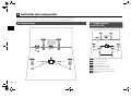
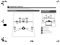
Set up the speakers in the room using the following diagram as a reference.
For information on other speaker systems, refer to “Owner’s Manual”.
1 Front speaker (L)
2 Front speaker (R)
3 Center speaker
4 Surround speaker (L)
5 Surround speaker (R)
6 Surround back speaker (L)
7 Surround back speaker (R)
9 Subwoofer
2 Placing speakers
5.1-channel system
12
39
45
10° to 30°10° to 30°
7.1-channel system
(RX-V575 only)
45
1
2
39
67
30 cm (1 ft) or more
10° to 30° 10° to 30°

En 3
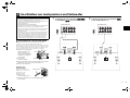
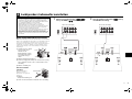
■ Connecting speaker cables
Speaker cables have two wires. One is for connecting the
negative (–) terminals of the unit and the speaker, and the
other is for the positive (+) terminals. If the wires are
colored to prevent confusion, connect the black wire to
the negative and the other wire to the positive terminals.
a Remove approximately 10
mm (3/8”) of insulation
from the ends of the
speaker cable and twist
the bare wires of the cable
firmly together.
b Loosen the speaker terminal.
c Insert the bare wires of the cable into the gap on the side
(upper right or bottom left) of the terminal.
d Tighten the terminal.
Using a banana plug
(U.S.A., Canada, China,
Australia and General
models only)
a Tighten the speaker
terminal.
b Insert a banana plug into the end of the terminal.
1
Connect the front speakers (1/2)
to the FRONT (//\) terminals.
2
Connect the center speaker (3) to the
CENTER terminal.
3 Connecting speakers/subwoofer
• (U.S.A. and Canada models only)
Under its default settings, the unit is configured for 8-ohm
speakers. When connecting 6-ohm speakers, set the unit’s
speaker impedance to “6 Ω MIN”. For details, see “Setting the
speaker impedance” in “Owner’s Manual”.
• (Except for U.S.A. and Canada models)
Use speakers with an impedance of at least 6 Ω.
• Use a subwoofer equipped with built-in amplifier.
• Before connecting the speakers, remove the unit’s power cable
from the AC wall outlet and turn off the subwoofer.
• Ensure that the core wires of the speaker cable do not touch
each other or come into contact with the unit’s metal areas. This
may damage the unit or the speakers. If the speaker cables
short circuit, “Check SP Wires” will appear on the front display
when the unit is turned on.
FRONT
aa
b
d
c
– (black)
+ (red)
FRONT
a
b
Banana plug
FRONT CENTER SURROUND
SPEAKERS
UBWOOFER
PRE OUT
2
1
12
3
45
9
The unit (rear)
FRONT CENTER SURROUND
SPEAKERS
SUBWOOFER
PRE OUT
2
1
12
3
45
9
The unit (rear)

4 En
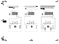
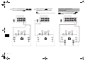
3
Connect the surround speakers (4/
5) to the SURROUND (//\)
terminals.
4
Connect the subwoofer (9) to the
SUBWOOFER PRE OUT jack.
• Use a subwoofer equipped with built-in amplifier.
Connect the surround back speakers (6/
7) to the SURROUND BACK (//\)
terminals.
FRONT CENTER SURROUND
SPEAKERS
SUBWOOFER
PRE OUT
2
1
12
3
45
9
The unit (rear)
FRONT CENTER SURROUND
SPEAKERS
UBWOOFER
PRE OUT
2
1
12
3
45
9
Audio pin cable
The unit (rear)
For 7.1-channel system (RX-V575 only)
FRONT CENTER SURROUND
SINGLE
SURROUND BACK BI AMP
/ZONE B
SPEAKERS
SUBWOOFER
PRE OUT
2
1
1
67
2
3
45
9
The unit (rear)

En 5
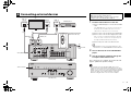
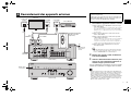
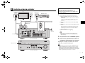
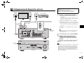
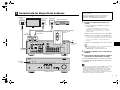
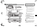
4 Connecting external devices
FRONT CENTER SURROUND
S NGLE
SURROUND BACK/BI AMP
ZONE B
AV 1
AV 2
AV 3
AV 5
AV 6
OPT C L OAX AL C AX AL O TCAL
(
V
)
COMPONENT
VI EO
COMPONENT
VID O
Y
AV
MONITOR OUT
OUT
UD O
AV 4
P
R
P
B
P
R
NETWORK
FM
ANTENNA
SPEAKERS
HDMI 1
(
BD DVD
)
HDMI 2
HDMI 3
HDMI 4
HDMI
OUT
A C
(
RAD O
)
UBWOO ER
PRE OU
2
1
HDMI 5
MHL
DC OUT
V 0 A
5V 1A
NET
)
INFO
MEMORY
PR SET
FM AM
TUNING
CONTROL
TV
BD
DVD
NET
RADIO
INPUT
SCENE
YPAO M C
PHONES
SILENT
C NEMA
STRA GHT
V DEO
D RECT
AUD O
VIDEO
VOLU ME
AUX
TONE
PROGRAM
5V 2 1A
VOLTAGE
SELECTOR
110V
-
120V
220V
-
240V
HDMIOPTICAL
HDMI
HDMI
HD
OUT
ARC
HDMI HDMI
HDMI
O
AV 4
OPTICAL
(TV)
O
H I 1
(
B VD
)
a
c
b
d
TV
Audio out
(optical)
HDMI in HDMI out
BD/DVD player
HDMI OUT
jack
HDMI 1 jack
AV 4 (OPTICAL) jack
The unit (rear)
To an AC wall
outlet
Turn on the unit
The unit (front)
VOLTAGE SELECTOR
(General model only)
1
Connect external devices to the unit.
a Connect a BD/DVD player to the unit with an HDMI
cable.
If the BD/DVD player is currently connected to the
TV directly with an HDMI cable, disconnect the
cable from the TV and connect it to this unit.
b Connect a TV to the unit with the other HDMI cable.
c Connect a TV to the unit with a digital optical cable.
This connection is required to play back TV audio
on the unit. This connection is not required if your
TV supports ARC (Audio Return Channel).
d Connect the power cable to an AC wall outlet.
• For information on how to connect radio antennas or other
external devices, see “PREPARATIONS” in “Owner’s Manual”.
2
Turn on the unit, the TV and the BD/DVD
player.
3
Use the TV remote control to change the
TV input to video from the unit.
The connections are complete. Proceed to the next
page to optimize the speaker settings.
• By connecting a TV to the unit with an HDMI cable, you can
configure the unit’s settings with the menu displayed on the TV. In
addition, you can select the on-screen menu language from English
(default), Japanese, French, German, Spanish, Russian, Italian and
Chinese. For details, refer to “Owner’s Manual”. In this guide,
illustrations of English menu screens are used as examples.
Before connecting the power cable (General model only)
Make sure you set the switch position of
VOLTAGE SELECTOR according to your local voltage.
Voltages are AC 110-120/220-240 V, 50/60 Hz.

6 En
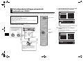
VOLUME HIGH CUT
CROSSOVER/
MIN MAXMIN MAX
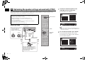
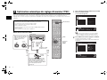
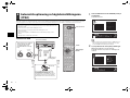
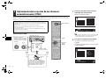
The Yamaha Parametric room Acoustic Optimizer (YPAO) function detects speaker connections, measures the
distances from them to your listening position(s), and then automatically optimizes the speaker settings, such as
volume balance and acoustic parameters, to suit your room.
Preparing for YPAO
5
Optimizing the speaker settings automatically (YPAO)
• During the measuring process, test tones are output at high volume. Ensure that
the test tones do not frighten small children. Also, refrain from using this function at
night when it may be a nuisance to others.
• During the measuring process, you cannot adjust the volume.
• During the measuring process, keep the room as quiet as possible.
• Do not connect headphones.
• Do not stand between the speakers and the YPAO microphone during the
measurement process (about 3 minutes).
• Move to the corner of the room or leave the room.
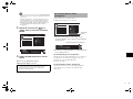
1
Connect the YPAO microphone to the
YPAO MIC jack on the front panel.
The following screen appears.
• To cancel the operation, disconnect the YPAO microphone, or
use the cursor keys to select “Exit” and press ENTER, before
starting the measurement.
2
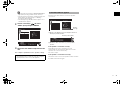
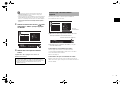
To start the measurement, press SETUP.
The measurement will start in 10 seconds.
The following screen appears on the TV when
the measurement finishes.
Auto Setup
Start
Exit
Press SETUP key
to Start
Power Amp Assign
Basic
VOL
SW
L
SL
C
SR
R
[SETUP]:Start
Auto Setup
Start
Exit
Measurement
Finished
Result
3 / 2 / 0.1 ch
3.0 / 10.5 m
3.0 / +10.0 dB
OK:ENTER
VOL
SW
L
SL
C
SR
R
Finished
SCENE
RETURN
VOLUME
ENHANCER
DIRECT
HDMI
MHL
TUNE
FM
INFO
MEMO
AM
PRESET
MOV E MUSIC
BD
D
MUTE
ENTER
TV
TV VOL TV CH
TOP
MENU
POP UP
MENU
D SPL
SOURCE
RECEIVER
CODE SET
OPT ON
SETUP
TUN NG
STRA GHT
SUR DECODE
NPUT
MUTE
9 0
10
ENT
7
MODE
TV
NET
RAD O
AUD O
1 2
3
NET
USB
V AUX
5
A
B
ZONE
4
5
1 2 3 4
SLEEP
6
SC
EN
E
RETURN
V
O
LUME
E
NHANCE
R
D
IREC
T
HDMI
MHL
A
V
TUNE
R
FM
I
NF
O
M
EM
O
RY
AM
P
RESET
M
O
V E
M
U
SI
C
BD
D
D
M
UT
E
TV
TV
V
O
L
TV
C
H
T
O
P
MEN
U
POP U
P
MEN
U
D S
PL
AY
CO
DE
S
ET
O
PT
O
N
TUN NG
S
TRA
GH
T
S
UR
D
E
CO
D
E
NP
U
T
MUTE
9
0
10
EN
T
6
5
8
7
1
2
3
4
MOD
E
TV
NET
RAD
O
A
UD
O
1
2
3
NE
T
US
B
V AU
X
5
A
B
Z
O
NE
4
5
1
2
3
4
S
LEE
P
6
SOURCE/RECEIVER
The unit (front)
Place the YPAO microphone at your
listening position (same height as your
ears). We recommend the use of a
tripod as a microphone stand. You can
use the tripod screws to fix the
microphone in place.
YPAO microphone
Listening position
Ear height
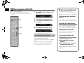
Cursor keys
ENTER
Turn on the subwoofer and set
the volume to half. If the
crossover frequency is
adjustable, set it to maximum.
SETUP

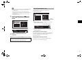
En 7
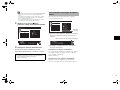
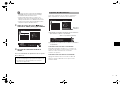
• If the cursor keys do not work, press SOURCE/RECEIVER (to
light up the key in orange) and then use the cursor keys.
• If any error message (such as E-1) or warning message (such
as W-2) appears, see “Error messages” or “Warning
messages” in “Owner’s Manual”.
• If the warning message “W-1:Out of Phase” appears, see “If
“W-1:Out of Phase” appears”.
3
Use the cursor keys (e/r) to select
“SAVE” (Save) and press ENTER.
4
Disconnect the YPAO microphone from the
unit.
This completes optimization of the speaker settings.
Follow the procedure below to check the speaker
connections.
a Check for the blinking of the front display’s indicator to
identify the problem speaker.
b Check the cable connections (+/-) of the problem
speaker.
If the speaker is connected correctly:
Depending on the type of speakers or room
environment, this message may appear even if the
speakers are connected correctly.
Proceed to step 3.
If the speaker is connected incorrectly:
Turn off the unit, reconnect the speaker cable, and then
try YPAO measurement again.
• The YPAO microphone is sensitive to heat, so should not be
placed anywhere where it could be exposed to direct sunlight or
high temperatures (such as on top of AV equipment).
Auto Setup
Start
Exit
Measurement
Finished
Result
3 / 2 / 0.1 ch
3.0 / 10.5 m
3.0 / +10.0 dB
SAVE
VOL
SW
L
SL
C
SR
R
>Save Cancel
If “W-1:Out of Phase” appears
Warning
message
Auto Setup
Start
Exit
Measurement
Finished
Result
3 / 2 / 0.1 ch
3.0 / 10.5 m
3.0 / +10.0 dB
W 1:Out of Phase
OK:ENTER
VOL
SW
L
SL
C
SR
R
W-1:PHASE
Problem speaker (blinks)

8 En
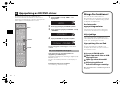
Now let’s play back a BD/DVD.
We recommend playing back multichannel audio
(5.1-channel or more) to feel surround sound produced
by the unit.
1
Press HDMI 1 to select “HDMI 1” as the
input source.
2
Start playback on the BD/DVD player.
3
Press STRAIGHT repeatedly to select
“STRAIGHT”.
4
Press VOLUME to adjust the volume.
This completes the basic setup procedure.
Sound is only being output from the front speakers
during multichannel audio playback
Check the digital audio output setting on the BD/DVD
player.
It may be set to 2-channel output (such as PCM).
No sound is coming from a specific speaker
See “Troubleshooting” in “Owner’s Manual”.
6 Playing back a BD/DVD
SCENE
RETURN
VOLUME
ENHANCER
D RECT
HDMI
MHL
TUNE
FM
NFO
MEMO
AM
PRESET
MOVIE MUS C
BD
DV
D
MUTE
ENTER
TV
TV VOL TV CH
TOP
MENU
POP UP
MENU
DISP
SOURCE
RECE VER
CODE SET
OPTION
SETUP
TUNING
STRAIGHT
SUR DECOD
INPUT
MUTE
9 0
10
ENT
7
MODE
TV
NET
RAD O
AUD O
1 2
3
NET
USB
V AUX
5
A
B
ZONE
4
5
1
SLEEP
6
SC
EN
E
R
ETURN
E
NHANCE
R
D
REC
T
HDMI
MHL
A
V
TUNE
R
FM
NF
O
M
EM
O
RY
AM
P
RESET
M
O
VIE
M
U
S
C
BD
DV
D
M
UT
E
ENTER
TV
TV
V
O
L
TV
C
H
T
O
P
MEN
U
POP U
P
MEN
U
D
I
S
P
AY
SOU
R
CE
R
E
C
E VER
CO
DE
S
ET
O
PTI
O
N
S
ETUP
TUNING
S
UR
D
E
CO
D
INP
U
T
MUTE
9
0
10
EN
T
6
5
8
7
1
2
3
4
MOD
E
TV
NET
RAD
O
A
UD
O
1
2
3
NE
T
US
B
V AU
X
5
A
B
Z
O
NE
4
5
S
LEE
P
6
HDMI 1
STRAIGHT
VOLUME
If surround sound is not working
SW
C
L
SL SR
R
HDMI1
VOL
SW
C
L
SL SR
R
VOL
STRAIGHT
SW
C
L
SL SR
R
Volume -30.0dB
VOL
Many more features!
The unit has various other functions.
Please refer to “Owner’s Manual” on the supplied
CD-ROM to help you get the most out of the unit.
Connecting other playback
devices
Connect audio devices (such as CD player),
game consoles, camcorders, and many others.
Selecting the sound mode
Select the desired sound program (CINEMA
DSP) or surround decoder suitable for movies,
music, games, sports programs, and other uses.
Playing back from iPod
By using a USB cable supplied with iPod, you
can enjoy iPod music on the unit.
■
Listening to FM/AM radio
■ Playing back music stored on
a USB storage device
■
Playing back the network
contents
■
Selecting the input source and
favorite settings at once
For more information, see “What you can do
with the unit”.

Fr 1
Manuel de
configuration rapide
Français
Vérifiez que les accessoires suivants sont fournis avec le produit.
Les câbles suivants (non fournis) sont requis pour l’installation du système décrit dans
le présent document.
• Câbles d’enceintes (en fonction du nombre d’enceintes)
• Câble HDMI (x2)
• Câble de broche audio (x1)
• Câble optique numérique (x1)
(inutile si votre téléviseur prend en charge la fonction ARC
[Audio Return Channel
])
1 Préparation
Accessoires
Télécommande Piles
(AAA, R03, UM-4) (x2)
Insérez les piles comme indiqué.
Antenne AM Antenne FM Microphone YPAO
CD-ROM
(Mode d’emploi)
Brochure sur la sécurité Manuel de configuration
rapide
• Les illustrations de l’unité principale et de la télécommande utilisées dans ce guide représentent le
modèle RX-V575 (modèle pour les États-Unis), sauf avis contraire.
*L’antenne FM fournie
dépend de la région
d’achat.
Câbles requis pour les raccordements
Ampli-tuner audio-vidéo
Ce document décrit l’installation d’un système à 5.1 ou 7.1 voies (RX-V575
uniquement) et explique comment restituer le son d’ambiance d’un disque
BD/DVD sur l’unité.
Afin de préserver l’environnement, le Mode d’emploi de ce produit est fourni sur
CD-ROM. Pour en savoir plus sur ce produit, reportez-vous au Mode d’emploi
fourni sur CD-ROM.
Pour télécharger ce guide ainsi que le « Mode d’emploi » au format PDF, rendez-
vous sur le site Web suivant :
http://download.yamaha.com/

2 Fr2 Fr
Installez les enceintes dans la pièce en vous reportant au diagramme suivant.
Pour obtenir des informations sur les autres systèmes d’enceinte, consultez le « Mode d’emploi ».
1 Enceinte avant (G)
2 Enceinte avant (D)
3 Enceinte centrale
4 Enceinte Surround (G)
5 Enceinte Surround (D)
6 Enceinte Surround arrière (G)
7 Enceinte Surround arrière (D)
9 Subwoofer
2 Installation des enceintes
Système à 5.1 voies
12
39
45
10° à 30°10° à 30°
Système à 7.1 voies
(RX-V575 uniquement)
45
1
2
39
67
30 cm ou plus
10° à 30° 10° à 30°

Fr 3
■
Raccordement des câbles d’enceinte
Les câbles d’enceinte sont composés de deux fils. L’un se
connecte aux bornes négatives (-) de l’appareil et de l’enceinte,
et l’autre aux bornes positives (+). Si les fils sont de couleurs
différentes afin d’éviter toute confusion, connectez le fil de
couleur noire aux bornes négatives et l’autre fil aux bornes
positives.
a Dénudez les extrémités du
câble d’enceinte sur environ
10 mm, puis torsadez
fermement les brins
dénudés du câble.
b Desserrez la borne
d’enceinte.
c Insérez les fils dénudés du
câble dans l’écartement sur le côté (supérieur droit ou
inférieur gauche) de la borne.
d Serrez la borne.
Utilisation d’une fiche
banane
(Modèles standard et destinés
aux États-Unis, au Canada, à la
Chine et à l’Australie
uniquement)
a Serrez la borne d’enceinte.
b Insérez la fiche banane dans
l’extrémité de la borne.
1
Raccordez les enceintes avant (1/
2) aux bornes FRONT (//\).
2
Raccordez l’enceinte centrale (3) à la
borne CENTER.
3 Raccordement des enceintes/du caisson de graves
• (Modèles pour les États-Unis et le Canada uniquement)
L’unité est configurée pour des enceintes 8 ohms par défaut.
Lorsque vous raccordez des enceintes 6 ohms, réglez
l’impédance d’enceinte de l’unité sur « 6 Ω MIN ». Pour plus
d’informations, reportez-vous à la section « Réglage de
l’impédance des enceintes » du « Mode d’emploi ».
• (Sauf pour les modèles destinés aux États-Unis et au Canada)
Utilisez des enceintes d’une impédance d’au moins 6 Ω.
• Utilisez un caisson de graves équipé d’un amplificateur intégré.
• Avant de raccorder les enceintes, retirez le câble d’alimentation
de l’unité de la prise secteur et éteignez le caisson de graves.
• Veillez à ce que les fils conducteurs du câble de l’enceinte ne
se touchent pas ou n’entrent pas en contact avec les parties
métalliques de l’unité. Ce contact risque d’endommager l’unité
ou les enceintes. Si un court-circuit survient au niveau des
câbles de l’enceinte, le message « Check SP Wires » apparaît
sur l’afficheur de la face avant lors de la mise sous tension de
l’unité.
FRONT
aa
b
d
c
– (noir)
+ (rouge)
FRONT
a
b
Fiche
banane
FRONT CENTER SURROUND
SPEAKERS
UBWOOFER
PRE OUT
2
1
12
3
45
9
L’unité (arrière)
FRONT CENTER SURROUND
SPEAKERS
SUBWOOFER
PRE OUT
2
1
12
3
45
9
L’unité (arrière)

4 Fr
3
Raccordez les enceintes d’ambiance
(4/5) aux bornes
SURROUND (//\).
4
Raccordez le caisson de graves (9)
à la prise SUBWOOFER PRE OUT.
• Utilisez un subwoofer équipé d’un amplificateur intégré.
Raccordez les enceintes surround arrière
(6/7) aux bornes SURROUND BACK
(//\).
FRONT CENTER SURROUND
SPEAKERS
SUBWOOFER
PRE OUT
2
1
12
3
45
9
L’unité (arrière)
FRONT CENTER SURROUND
SPEAKERS
UBWOOFER
PRE OUT
2
1
12
3
45
9
Câble de broche audio
L’unité (arrière)
Pour le système à 7.1 voies (RX-V575
uniquement)
FRONT CENTER SURROUND
SINGLE
SURROUND BACK BI AMP
/ZONE B
SPEAKERS
SUBWOOFER
RE OUT
2
1
1
67
2
3
45
9
L’unité (arrière)

Fr 5
4 Raccordement des appareils externes
FRONT CENTER SURROUND
S NGLE
SURROUND BACK/BI AMP
ZONE B
AV 1
AV 2
AV 3
AV 5
AV 6
OPT C L OAX AL C AX AL O T CAL
(
V
)
COMPONENT
VI EO
COMPONENT
VID O
Y
AV
MONITOR OUT
OUT
UD O
AV 4
P
R
P
B
P
R
NETWORK
FM
ANTENNA
SPEAKERS
HDMI 1
(
BD DVD
)
HDMI 2
HDMI 3
HDMI 4
HDMI
OUT
A C
(
RAD O
)
UBWOO ER
PRE OU
2
1
HDMI 5
MHL
DC OUT
V 0 A
5V 1A
NET
)
INFO
MEMORY
PR SET
FM AM
TUNING
CONTROL
TV
BD
DVD
NET
RADIO
INPUT
SCENE
YPAO M C
PHONES
SILENT
C NEMA
STRA GHT
V DEO
D RECT
AUD O
VIDEO
VOLU ME
AUX
TONE
PROGRAM
5V 2 1A
VOLTAGE
SELECTOR
110V
-
120V
220V
-
240V
HDMIOPTICAL
HDMI
HDMI
HD
OUT
ARC
HDMI HDMI
HDMI
O
AV 4
OPTICAL
(TV)
O
H I 1
(
B VD
)
a
c
b
d
Téléviseur
Sortie audio
(optique)
Entrée HDMI Sortie HDMI
Lecteur BD/DVD
Prise
HDMI OUT
Prise HDMI 1
Prise AV 4
(OPTICAL)
L’unité (arrière)
Branchement
sur une prise
secteur
Mettre l’unité
sous tension
L’unité (avant)
VOLTAGE SELECTOR
(Modèles Standard
uniquement)
1
Raccordez les appareils externes à l’unité.
a Raccordez un lecteur BD/DVD à l’unité au moyen
d’un câble HDMI.
Si le lecteur BD/DVD est actuellement directement
raccordé au téléviseur à l’aide d’un câble HDMI,
débranchez ce câble du téléviseur et raccordez-le
à cette unité.
b Raccordez un téléviseur à l’unité au moyen de
l’autre câble HDMI.
c Raccordez un téléviseur à l’unité au moyen d’un
câble optique numérique.
Ce raccordement est nécessaire si vous souhaitez
restituer le son TV sur l’unité. Ce raccordement
n’est pas nécessaire si votre téléviseur prend en
charge la fonction ARC (Audio Return Channel).
d Raccordez le câble d’alimentation à une prise
électrique murale.
• Pour plus d’informations sur le raccordement des antennes
radio ou des autres appareils externes, reportez-vous à la
section « PRÉPARATION » du « Mode d’emploi ».
2
Mettez sous tension, l’unité, le téléviseur
et le lecteur BD/DVD.
3
Utilisez la télécommande du téléviseur pour
changer la source d’entrée du téléviseur et
afficher l’image à partir de l’unité.
Les raccordements sont terminés. Passez à la page
suivante pour optimiser les réglages des enceintes.
• Lorsque le téléviseur est raccordé à l’unité par un câble HDMI, vous
pouvez configurer les réglages de cette dernière à l’aide du menu qui
s’affiche sur le téléviseur. Par ailleurs, vous pouvez sélectionner la
langue souhaitée dans le menu affiché à l’écran parmi les langues
suivantes : anglais (par défaut), japonais, français, allemand, espagnol,
russe, italien et chinois. Pour plus d’informations, reportez-vous au
« Mode d’emploi ». Des illustrations d’écrans de menus anglais sont
utilisées comme exemples dans ce guide.
Avant de raccorder le câble d’alimentation (modèle
standard uniquement)
Vérifiez que vous sélectionnez la position de permutation de
VOLTAGE SELECTOR en fonction de la tension locale. Les
tensions sont CA 110-120/220-240 V, 50/60 Hz.

6 Fr
La fonction Yamaha Parametric room Acoustic Optimizer (YPAO) permet de détecter les raccordements des enceintes
et de mesurer la distance entre ces dernières et la position d’écoute. Elle optimise ensuite automatiquement les
réglages des enceintes tels que les paramètres d’équilibre du volume et les paramètres acoustiques qui conviennent
à la pièce.
Préparation à la fonction YPAO
5
Optimisation automatique des réglages d’enceintes (YPAO)
• Lors de la mesure, des signaux test sont restitués à un volume élevé. Assurez-vous
que le signal test n’effraie pas les jeunes enfants. Évitez également d’utiliser cette
fonction la nuit, où elle peut constituer une nuisance pour les autres.
• Lors de la mesure, vous ne pouvez pas régler le volume.
• Faites en sorte que la pièce soit le plus calme possible.
• Ne raccordez pas d’écouteurs.
• Ne restez pas entre les enceintes et le microphone YPAO pendant la mesure
(environ 3 minutes).
• Placez-vous dans un coin de la pièce ou quittez-la.
VOLUME HIGH CUT
CROSSOVER/
MIN MAXMIN MAX
L’unité (avant)
Placez le microphone YPAO à votre
position d’écoute (à hauteur d’oreilles).
Nous conseillons l’utilisation d’un
trépied comme support de microphone.
Lorsque vous utilisez un trépied, utilisez
les vis du trépied pour fixer le
microphone.
Microphone YPAO
Position d’écoute
Hauteur
d’oreille
Allumez le caisson de graves et
réglez le volume à moitié. Si la
fréquence de coupure est
réglable, réglez-la sur le
maximum.
1
Raccordez le microphone YPAO à la prise YPAO
MIC sur le panneau avant.
L’écran suivant apparaît.
• Pour annuler l’opération, débranchez le microphone YPAO ou
utilisez les touches de curseur pour sélectionner « Exit » et
appuyez sur ENTER, avant le début de l’opération de mesure.
2
Pour démarrer la mesure, appuyez sur SETUP.
La mesure commence dans 10 secondes.
Lorsque la mesure est terminée, l’écran suivant apparaît sur le
moniteur TV.
Auto Setup
Start
Exit
Press SETUP key
to Start
Power Amp Assign
Basic
VOL
SW
L
SL
C
SR
R
[SETUP]:Start
Auto Setup
Start
Exit
Measurement
Finished
Result
3 / 2 / 0.1 ch
3.0 / 10.5 m
3.0 / +10.0 dB
OK:ENTER
VOL
SW
L
SL
C
SR
R
Finished
SCENE
RETURN
ENHANCER
DIRECT
HDMI
MHL
TUNE
FM
INFO
MEMO
AM
PRESET
MOV E MUSIC
BD
D
D
MUTE
ENTER
TV
TV VOL TV CH
TOP
MENU
POP UP
MENU
D SPL
SOURCE
RECEIVER
CODE SET
OPT ON
SETUP
TUN NG
STRA GHT
SUR DECODE
NPUT
MUTE
9 0
10
ENT
7
MODE
TV
NET
RAD O
AUD O
1 2
3
NET
USB
V AUX
5
A
B
ZONE
4
5
1 2 3 4
SLEEP
6
SC
EN
E
RETURN
E
NHANCE
R
D
IREC
T
HDMI
MHL
A
V
TUNE
R
FM
I
NF
O
M
EM
O
RY
AM
P
RESET
M
O
V E
M
U
SI
C
BD
D
D
M
UT
E
TV
TV
V
O
L
TV
C
H
T
O
P
MEN
U
POP U
P
MEN
U
D S
PL
AY
CO
DE
S
ET
O
PT
O
N
TUN NG
S
TRA
GH
T
S
UR
D
E
CO
D
E
NP
U
T
MUTE
9
0
10
EN
T
6
5
8
7
1
2
3
4
MOD
E
TV
NET
RAD
O
A
UD
O
1
2
3
NE
T
US
B
V AU
X
5
A
B
Z
O
NE
4
5
1
2
3
4
S
LEE
P
6
SOURCE/RECEIVER
Touches de
curseur
ENTER
SETUP

Fr 7
• Si les touches de curseur ne fonctionnent pas, appuyez sur
SOURCE/RECEIVER (la touche s’allume en orange), puis
essayez à nouveau de les utiliser.
• Si un message d’erreur (par exemple E-1) ou d’avertissement (par
exemple W-2) apparaît, reportez-vous aux sections « Messages
d’erreur » ou « Messages d’avertissement » du « Mode d’emploi ».
• Si le message d’avertissement « W-1:Out of Phase » apparaît,
reportez-vous à la section « Si le message « W-1:Out of Phase »
apparaît ».
3
Utilisez les touches du curseur (e/r) pour
sélectionner « SAVE » (Save) et appuyez
sur ENTER.
4
Débranchez le microphone YPAO de
l’unité.
L’optimisation des réglages d’enceintes est
maintenant terminée.
Suivez la procédure ci-dessous pour vérifier les
raccordements de l’enceinte.
a Observez le témoin clignotant de l’afficheur de la face
avant pour identifier l’enceinte défectueuse.
b Contrôlez les raccordements des câbles (+ et -) de
l’enceinte défectueuse.
Si l’enceinte est correctement raccordée :
Selon le type d’enceintes ou l’environnement,
ce message peut apparaître, même si les enceintes
sont correctement raccordées.
Passez à l’étape 3.
Si l’enceinte n’est pas correctement raccordée :
Mettez l’unité hors tension et raccordez à nouveau le
câble d’enceinte, puis essayez à nouveau d’effectuer la
mesure YPAO.
• Le microphone YPAO est sensible à la chaleur. Ne le placez
pas dans un endroit où il pourrait être exposé directement à la
lumière du soleil ou à des températures élevées (sur un
équipement AV, etc.).
Auto Setup
Start
Exit
Measurement
Finished
Result
3 / 2 / 0.1 ch
3.0 / 10.5 m
3.0 / +10.0 dB
SAVE
VOL
SW
L
SL
C
SR
R
>Save Cancel
Si le message « W-1:Out of Phase »
apparaît
Message
d’avertissement
Auto Setup
Start
Exit
Measurement
Finished
Result
3 / 2 / 0.1 ch
3.0 / 10.5 m
3.0 / +10.0 dB
W 1:Out of Phase
OK:ENTER
VOL
SW
L
SL
C
SR
R
W-1:PHASE
Enceinte défectueuse (clignote)

8 Fr
Voyons maintenant comment lire un disque BD/DVD.
Pour sentir les effets d’ambiance sonore produits par
l’unité, nous vous recommandons de lire les disques
avec le système audio multivoies (5.1 voies et plus).
1
Appuyez sur HDMI 1 pour sélectionner
« HDMI 1 » comme source d’entrée.
2
Commencez la lecture sur le lecteur
BD/DVD.
3
Appuyez à plusieurs reprises sur STRAIGHT
pour sélectionner « STRAIGHT ».
4
Appuyez sur VOLUME pour régler
le volume.
La procédure d’installation de base est maintenant
terminée.
Lors de la lecture à l’aide du système audio
multivoies, le son est restitué uniquement par
les enceintes avant
Vérifiez le réglage de la sortie audio numérique du
lecteur BD/DVD.
Il est peut-être réglé pour restituer un son à 2 voies
(PCM par exemple).
Une enceinte spécifique n’émet aucun son
Reportez-vous à la section « Guide de dépannage »
du « Mode d’emploi ».
6 Lecture d’un disque BD/DVD
SCENE
RETURN
VOLUME
ENHANCER
D RECT
HDMI
MHL
TUNE
FM
NFO
MEMO
AM
PRESET
MOVIE MUS C
BD
DV
D
MUTE
ENTER
TV
TV VOL TV CH
TOP
MENU
POP UP
MENU
DISP
SOURCE
RECE VER
CODE SET
OPTION
SETUP
TUNING
STRAIGHT
SUR DECOD
INPUT
MUTE
9 0
10
ENT
7
MODE
TV
NET
RAD O
AUD O
1 2
3
NET
USB
V AUX
5
A
B
ZONE
4
5
1
SLEEP
6
SC
EN
E
R
ETURN
E
NHANCE
R
D
REC
T
HDMI
MHL
A
V
TUNE
R
FM
NF
O
M
EM
O
RY
AM
P
RESET
M
O
VIE
M
U
S
C
BD
DV
D
M
UT
E
ENTER
TV
TV
V
O
L
TV
C
H
T
O
P
MEN
U
POP U
P
MEN
U
D
I
S
P
AY
SOU
R
CE
R
E
C
E VER
CO
DE
S
ET
O
PTI
O
N
S
ETUP
TUNING
S
UR
D
E
CO
D
INP
U
T
MUTE
9
0
10
EN
T
6
5
8
7
1
2
3
4
MOD
E
TV
NET
RAD
O
A
UD
O
1
2
3
NE
T
US
B
V AU
X
5
A
B
Z
O
NE
4
5
S
LEE
P
6
HDMI 1
STRAIGHT
VOLUME
Si le système de son d’ambiance ne
fonctionne pas
SW
C
L
SL SR
R
HDMI1
VOL
SW
C
L
SL SR
R
VOL
STRAIGHT
SW
C
L
SL SR
R
Volume -30.0dB
VOL
Encore plus de
fonctions !
L’unité propose diverses autres fonctions.
Reportez-vous au « Mode d’emploi » sur le
CD-ROM fourni pour savoir comment utiliser
l’unité de manière optimale.
Raccordement d’autres
appareils de lecture
Raccordez des appareils audio (lecteurs CD et
autres), consoles de jeux, caméscopes, etc.
Sélection du mode sonore
Sélectionnez le programme sonore souhaité
(CINEMA DSP) ou le décodeur d’ambiance qui
convient aux films, à la musique, aux jeux, aux
programmes sportifs, etc.
Écoute de musique à partir
d’un iPod
Grâce au câble USB fourni avec l’iPod, vous
pouvez écouter votre musique sur l’unité.
■
Écoute d’émission FM/AM
■ Lecture de musique stockée sur
un dispositif de stockage USB
■
Lecture de contenus réseau
■
Sélection simultanée de la source
et des paramètres favoris
Pour plus d’informations, reportez-vous à la
section « Fonctions de l’unité ».

De 1
Prüfen Sie, ob das folgende Zubehör im Lieferumfang des Produkts enthalten ist.
Die folgenden Kabel (nicht mitgeliefert) sind erforderlich, um das in diesem Dokument
beschriebene System aufzubauen.
• Lautsprecherkabel (je nach Anzahl der Lautsprecher)
• HDMI-Kabel (x 2)
• Audio-Cinchkabel (x 1)
• Optisches Digitalkabel (x 1)
(nicht erforderlich, wenn Ihr Fernseher ARC unterstützt [Audio
Return Channel
])
1 Vorbereitung
Zubehör
Fernbedienung Batterien
(AAA, R03, UM-4) (x 2)
Setzen Sie die Batterien in der
richtigen Ausrichtung ein.
AM-Antenne FM-Antenne YPAO-Mikrofon
CD-ROM
(Bedienungsanleitung)
Sicherheitsbroschüre Anleitung zur
Schnelleinrichtung
• Die Abbildungen des Hauptgeräts und der Fernbedienung in dieser Anleitung stammen vom
US-amerikanischen Modell des RX-V575.
* Je nach Erwerbsort ist die
mitgelieferte FM-Antenne
unterschiedlich ausgeführt.
Erforderliche Anschlusskabel
Anleitung zur
Schnelleinrichtung
Deutsch
AV-Receiver
Dieses Dokument beschreibt, wie ein 5.1- oder 7.1-Kanal-System (nur RX-V575) ein-
gerichtet und Surround-Sound von BD/DVD über das Gerät wiedergegeben wird.
Um die Umwelt zu schonen, wird die Bedienungsanleitung für dieses
Produkt auf CD-ROM ausgeliefert. Weitere Einzelheiten über dieses
Produkt finden Sie in der Bedienungsanleitung auf der beiliegenden
CD-ROM.
PDF-Versionen dieser Anleitung zur Schnelleinrichtung sowie der „Bedienungs-
anleitung“ können von der folgenden Website heruntergeladen werden.
http://download.yamaha.com/

2 De2 De
Stellen Sie die Lautsprecher im Raum auf, während Sie sich an der folgenden Abbildung orientieren.
Informationen zu anderen Lautsprechersystemen entnehmen Sie bitte der „Bedienungsanleitung“.
1 Front-Lautsprecher (L)
2 Front-Lautsprecher (R)
3 Center-Lautsprecher
4 Surround-Lautsprecher (L)
5 Surround-Lautsprecher (R)
6 Hinterer Surround-Lautsprecher (L)
7 Hinterer Surround-Lautsprecher (R)
9 Subwoofer
2 Aufstellen der Lautsprecher
5.1-Kanal-System
12
39
45
10° bis 30°10° bis 30°
7.1-Kanal-System
(nur RX-V575)
45
1
2
39
67
mindestens 30 cm
10° bis 30° 10° bis 30°

De 3
■ Anschließen der Lautsprecherkabel
Lautsprecherkabel haben zwei Adern. Eine davon wird am
negativen (–) Anschluss von Gerät und Lautsprecher
angeschlossen, die andere am positiven (+) Anschluss. Wenn die
Adern farbkodiert sind, um Verwechslungen zu verhindern, sollten
Sie die schwarz gefärbte Ader an der negativen Polklemme und
die andere Ader an der positiven Polklemme anschließen.
a
Entfernen Sie vom Ende jedes
Lautsprecherkabels circa 10
mm der Isolierung, und
verdrehen Sie die Metallfäden
der blanken Litze möglichst
fest miteinander.
b
Lösen Sie die
Lautsprecherklemme.
c
Führen Sie die blanke Litze des Lautsprecherkabels in die seitliche
Öffnung (oben rechts oder unten links) der Klemme ein.
d
Ziehen Sie die Klemme fest.
Verwenden eines
Bananensteckers
(nur US-amerikanisches,
kanadisches, chinesisches,
australisches und
Universalmodell)
a Ziehen Sie die
Lautsprecherklemme fest.
b
Stecken Sie einen Bananenstecker in die Öffnung an der
Schraubklemme.
1
Schließen Sie die Front-Lautsprecher (
1
/
2
)
an den
FRONT (/
/
\
)
-Buchsen an.
2
Schließen Sie den Center-Lautsprecher (3)
an der CENTER-Buchse an.
3 Anschließen von Lautsprechern und Subwoofer
• (nur Modelle für USA und Kanada)
Das Gerät ist werksseitig für 8-Ohm-Lautsprecher konfiguriert. Beim
Anschluss von 6-Ohm-Lautsprechern stellen Sie die
Lautsprecherimpedanz-Einstellung auf „6 Ω MIN“ ein. Näheres siehe
unter „Einstellen der Lautsprecherimpedanz” in der
„Bedienungsanleitung“.
• (Außer den Modellen für USA und Kanada)
Verwenden Sie Lautsprecher mit einer Impedanz von mindestens 6
Ω
.
• Verwenden Sie einen Subwoofer mit integriertem Verstärker.
• Bevor Sie die Lautsprecher anschließen, trennen Sie das Netzkabel
des Geräts von der Netzspannungsversorgung, und schalten Sie
den Subwoofer aus.
• Achten Sie darauf, dass die Leitungsadern des Lautsprecherkabels
nicht einander berühren und auch nicht mit metallenen Bereichen
am Gerät in Kontakt kommen. Dadurch könnten das Gerät oder die
Lautsprecher beschädigt werden. Im Fall eines Kurzschlusses der
Lautsprecherkabel wird die Meldung „Check SP Wires“ auf dem
Frontblende-Display angezeigt, wenn das Gerät einschaltet wird.
FRONT
aa
b
d
c
– (Schwarz)
+ (Rot)
FRONT
a
b
Bananenstecker
FRONT CENTER SURROUND
SPEAKERS
UBWOOFER
PRE OUT
2
1
12
3
45
9
Gerät (Rückseite)
FRONT CENTER SURROUND
SPEAKERS
SUBWOOFER
PRE OUT
2
1
12
3
45
9
Gerät (Rückseite)
Strona się ładuje...
Strona się ładuje...
Strona się ładuje...
Strona się ładuje...
Strona się ładuje...
Strona się ładuje...
Strona się ładuje...
Strona się ładuje...
Strona się ładuje...
Strona się ładuje...
Strona się ładuje...
Strona się ładuje...
Strona się ładuje...
Strona się ładuje...
Strona się ładuje...
Strona się ładuje...
Strona się ładuje...
Strona się ładuje...
Strona się ładuje...
Strona się ładuje...
Strona się ładuje...
Strona się ładuje...
Strona się ładuje...
Strona się ładuje...
Strona się ładuje...
Strona się ładuje...
Strona się ładuje...
Strona się ładuje...
Strona się ładuje...
Strona się ładuje...
Strona się ładuje...
Strona się ładuje...
Strona się ładuje...
Strona się ładuje...
Strona się ładuje...
Strona się ładuje...
Strona się ładuje...
Strona się ładuje...
-
 1
1
-
 2
2
-
 3
3
-
 4
4
-
 5
5
-
 6
6
-
 7
7
-
 8
8
-
 9
9
-
 10
10
-
 11
11
-
 12
12
-
 13
13
-
 14
14
-
 15
15
-
 16
16
-
 17
17
-
 18
18
-
 19
19
-
 20
20
-
 21
21
-
 22
22
-
 23
23
-
 24
24
-
 25
25
-
 26
26
-
 27
27
-
 28
28
-
 29
29
-
 30
30
-
 31
31
-
 32
32
-
 33
33
-
 34
34
-
 35
35
-
 36
36
-
 37
37
-
 38
38
-
 39
39
-
 40
40
-
 41
41
-
 42
42
-
 43
43
-
 44
44
-
 45
45
-
 46
46
-
 47
47
-
 48
48
-
 49
49
-
 50
50
-
 51
51
-
 52
52
-
 53
53
-
 54
54
-
 55
55
-
 56
56
-
 57
57
-
 58
58


Yamaha RX-V475 Instrukcja obsługi
- Kategoria
- Odbiorca
- Typ
- Instrukcja obsługi
- Niniejsza instrukcja jest również odpowiednia dla
w innych językach
- čeština: Yamaha RX-V475 Návod k obsluze
- español: Yamaha RX-V475 El manual del propietario
- italiano: Yamaha RX-V475 Manuale del proprietario
- Deutsch: Yamaha RX-V475 Bedienungsanleitung
- svenska: Yamaha RX-V475 Bruksanvisning
- français: Yamaha RX-V475 Le manuel du propriétaire
- Türkçe: Yamaha RX-V475 El kitabı
- English: Yamaha RX-V475 Owner's manual
- dansk: Yamaha RX-V475 Brugervejledning
- suomi: Yamaha RX-V475 Omistajan opas
- Nederlands: Yamaha RX-V475 de handleiding
- română: Yamaha RX-V475 Manualul proprietarului
Powiązane artykuły
-
Yamaha HTR-5066 Instrukcja obsługi
-
Yamaha RX-V771 Instrukcja instalacji
-
Yamaha RX-V375 Instrukcja obsługi
-
Yamaha HTR-3066 Instrukcja obsługi
-
Yamaha RXA830BL Instrukcja obsługi
-
Yamaha RX-S600 Instrukcja obsługi
-
Yamaha RX-A2030 Instrukcja obsługi
-
Yamaha RX-A1030 instrukcja
-
Yamaha RX-V775 Instrukcja obsługi
-