
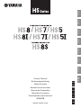
POWERED SPEAKER SYSTEM
//
Owner’s Manual
Bedienungsanleitung
Mode d'emploi
Manual de instrucciones
Manual do Proprietário
Manuale di istruzioni
Руководство пользователя
//
DE
FR
ES
PT
IT
RU
JA
EN
EnglishDeutschFrançaisEspañolPortuguêsItalianoРусский

Explanation of Graphical Symbols
Explication des symboles
The lightning flash with arrowhead symbol within an equilateral triangle is intended to alert the user to the presence of uninsulated
“dangerous voltage” within the product’s enclosure that may be of sufficient magnitude to constitute a risk of electric shock to persons.
L’éclair avec une flèche à l’intérieur d’un triangle équilatéral est destiné à attirer l’attention de l’utilisateur sur la présence d’une « tension
dangereuse » non isolée à l’intérieur de l’appareil, pouvant être suffisamment élevée pour constituer un risque d’électrocution.
The exclamation point within an equilateral triangle is intended to alert the user to the presence of important operating and maintenance
(servicing) instructions in the literature accompanying the product.
Le point d’exclamation à l’intérieur d’un triangle équilatéral est destiné à attirer l’attention de l’utilisateur sur la présence d’instructions
importantes sur l’emploi ou la maintenance (réparation) de l’appareil dans la documentation fournie.
IMPORTANT SAFETY
INSTRUCTIONS
1 Read these instructions.
2 Keep these instructions.
3 Heed all warnings.
4 Follow all instructions.
5 Do not use this apparatus near water.
6 Clean only with dry cloth.
7 Do not block any ventilation openings. Install in accordance with the
manufacturer’s instructions.
8 Do not install near any heat sources such as radiators, heat registers,
stoves, or other apparatus (including amplifiers) that produce heat.
9 Do not defeat the safety purpose of the polarized or grounding-type
plug. A polarized plug has two blades with one wider than the other. A
grounding type plug has two blades and a third grounding prong. The
wide blade or the third prong are provided for your safety. If the pro-
vided plug does not fit into your outlet, consult an electrician for
replacement of the obsolete outlet.
10 Protect the power cord from being walked on or pinched particularly
at plugs, convenience receptacles, and the point where they exit from
the apparatus.
11 Only use attachments/accessories specified by the manufacturer.
12 Use only with the cart, stand, tripod, bracket, or
table specified by the manufacturer, or sold with
the apparatus. When a cart is used, use caution
when moving the cart/apparatus combination to
avoid injury from tip-over.
13 Unplug this apparatus during lightning storms
or when unused for long periods of time.
14 Refer all servicing to qualified service personnel. Servicing is
required when the apparatus has been damaged in any way, such as
power-supply cord or plug is damaged, liquid has been spilled or
objects have fallen into the apparatus, the apparatus has been
exposed to rain or moisture, does not operate normally, or has been
dropped.
(UL60065_03)
PRÉCAUTIONS CONCER-
NANT LA SÉCURITÉ
1 Lire ces instructions.
2 Conserver ces instructions.
3 Tenir compte de tous les avertissements.
4 Suivre toutes les instructions.
5 Ne pas utiliser ce produit à proximité d’eau.
6 Nettoyer uniquement avec un chiffon propre et sec.
7 Ne pas bloquer les orifices de ventilation. Installer l’appareil confor-
mément aux instructions du fabricant.
8 Ne pas installer l’appareil à proximité d’une source de chaleur comme
un radiateur, une bouche de chaleur, un poêle ou tout autre appareil
(y compris un amplificateur) produisant de la chaleur.
9 Ne pas modifier le système de sécurité de la fiche polarisée ou de la
fiche de terre. Une fiche polarisée dispose de deux broches dont une
est plus large que l’autre. Une fiche de terre dispose de deux broches
et d’une troisième pour le raccordement à la terre. Cette broche plus
large ou cette troisième broche est destinée à assurer la sécurité de
l’utilisateur. Si la fiche équipant l’appareil n’est pas compatible avec
les prises de courant disponibles, faire remplacer les prises par un
électricien.
10 Acheminer les cordons d’alimentation de sorte qu’ils ne soient pas
piétinés ni coincés, en faisant tout spécialement attention aux fiches,
prises de courant et au point de sortie de l’appareil.
11 Utiliser exclusivement les fixations et accessoires spécifiés par le
fabricant.
12 Utiliser exclusivement le chariot, le stand, le tré-
pied, le support ou la table recommandés par le
fabricant ou vendus avec cet appareil. Si l’appa-
reil est posé sur un chariot, déplacer le chariot
avec précaution pour éviter tout risque de chute
et de blessure.
13 Débrancher l’appareil en cas d’orage ou
lorsqu’il doit rester hors service pendant une période prolongée.
14 Confier toute réparation à un personnel qualifié. Faire réparer l’appa-
reil s’il a subi tout dommage, par exemple si la fiche ou le cordon
d’alimentation est endommagé, si du liquide a coulé ou des objets
sont tombés à l’intérieur de l’appareil, si l’appareil a été exposé à la
pluie ou à de l’humidité, si l’appareil ne fonctionne pas normalement
ou est tombé.
(UL60065_03)
The above warning is located on the rear of the unit. L’avertissement ci-dessus est situé sur l’arrière de l’unité.
CAUTION:
TO REDUCE THE RISK OF ELECTRIC SHOCK,
DO NOT REMOVE COVER (OR BACK).
NO USER-SERVICEABLE PARTS INSIDE.
REFER SERVICING TO QUALIFIED SERVICE PERSONNEL.
ATTENTION :
POUR RÉDUIRE LES RISQUES D'ÉLECTROCUTION, NE PAS RETIRER
LE CAPOT (OU LE DOS). NE CONTIENT PAS DE PIÈCES NÉCESSITANT
L'INTERVENTION DE L'UTILISATEUR. POUR TOUTE INTERVENTION,
FAIRE APPEL À DES PROFESSIONNELS QUALIFIÉS.
ATTENTION
RISQUE DE CHOC
ELECTRIQUE-NE PAS OUVRIR
WARNING
TO REDUCE THE RISK OF FIRE OR ELECTRIC SHOCK, DO NOT
EXPOSE THIS APPARATUS TO RAIN OR MOISTURE.
AVERTISSEMENT
POUR RÉDUIRE LES RISQUES D’INCENDIE OU DE DÉCHARGE
ÉLECTRIQUE, N’EXPOSEZ PAS CET APPAREIL À LA PLUIE OU À
L’HUMIDITÉ.

HS8/HS7/HS5/HS8I/HS7I/HS5I/HS8S Owner’s Manual
3
English
Contents
Features.................................................. 3
Included Items (please check).............. 3
PRECAUTIONS....................................... 4
NOTICE ................................................... 5
Rear Panel .............................................. 6
Setup....................................................... 8
Troubleshooting................................... 12
Specifications ...................................... 89
Dimensions .......................................... 89
Performance Graph ............................. 90
Block Diagram...................................... 90
Tilt Angle (HS8I/HS7I/HS5I only)......... 91
• The illustrations as shown in this manual are for
instructional purposes only.
• The company names and product names in this manual
are the trademarks or registered trademarks of their
respective companies.
• In this manual (unless indicated otherwise), “HS8” refers
to both the HS8 and HS8I, “HS7” refers to the HS7 and
HS7I and “HS5” refers to the HS5 and HS5I.
Features
Accurate, detailed reproduction of the source.
A choice of three full-range models plus one
high-performance subwoofer makes it easy to
create systems that are ideally matched to any
monitoring environment.
Simple 2-way design in the full-range models,
with optimally matched high and low frequency
units.
Response-tailoring controls match speaker
output to a wide range of acoustic spaces.
In addition to studio standard XLR connectors,
phone jacks allow direct connection of electronic
musical instruments and other sources.
Included Items
(please check)
•Power cord
• Screws for bracket installation
(2; HS8I/HS7I/HS5I only)
• Owner’s Manual (this book)
Optional Items
For HS8I/HS7I
• Baton bracket BBS251
• Ceiling bracket BCS251
• Wall bracket BWS251
• Wall bracket / ceiling bracket BWS50
For HS5I
• Wall bracket / ceiling bracket BWS20
• Ceiling bracket BCS20
Thank you for choosing a Yamaha powered
monitor speaker or powered subwoofer.
In order to take maximum advantage of the
speaker’s features and ensure maximum
performance and longevity, please read this
manual carefully before using powered
monitor speaker or powered subwoofer.
Keep the manual in a safe place for future
reference.

HS8/HS7/HS5/HS8I/HS7I/HS5I/HS8S Owner’s Manual
4
PRECAUTIONS
PLEASE READ CAREFULLY BEFORE
PROCEEDING
Please keep this manual in a safe place for
future reference.
This product is designed for accurate sound monitoring during
audio recording, editing, mixing and other applications. Do not
use for any purpose other than as a speaker. Those who are
unfamiliar with handling or those who can not handle according to
this manual, should be supervised by responsible persons to
ensure safety.
WARNING
Always follow the basic precautions listed below to avoid the
possibility of serious injury or even death from electrical
shock, short-circuiting, damages, fire or other hazards. These
precautions include, but are not limited to, the following:
If you notice any abnormality
• If any of the following problems occur, immediately turn off the power
switch and disconnect the electric plug from the outlet.
- The power cord or plug becomes frayed or damaged.
- Unusual smells or smoke are emitted.
- Some object, or water has been dropped into the product.
- There is a sudden loss of sound during use of the product.
- Cracks or other visible damage appear on the product.
Then have the product inspected or repaired by qualified Yamaha
service personnel.
Power supply/Power cord
• Do not place the power cord near heat sources such as heaters or
radiators, and do not excessively bend or otherwise damage the cord,
place heavy objects on it, or place it in a position where anyone could
walk on, trip over, or roll anything over it.
• Only use the voltage specified as correct for the product. The required
voltage is printed on the name plate of the product.
• Use only the supplied power cord/plug.
If you intend to use the product in an area other than in the one you
purchased, the included power cord may not be compatible. Please
check with your Yamaha dealer.
• Check the electric plug periodically and remove any dirt or dust which
may have accumulated on it.
• Make sure to fully insert the electric plug to prevent electric shocks or
fire.
• When setting up the product, make sure that the AC outlet you are using
is easily accessible. If some trouble or malfunction occurs, immediately
turn off the power switch and disconnect the plug from the outlet. Even
when the power switch is turned off, as long as the power cord is not
unplugged from the wall AC outlet, the product will not be disconnected
from the power source.
• Remove the electric plug from the outlet when the product is not to be
used for extended periods of time.
• Do not touch the product or the electric plug during an electrical storm.
• Be sure to connect to an appropriate outlet with a protective grounding
connection. Improper grounding can result in electrical shock, fire, or
damage.
Do not open
• This product contains no user-serviceable parts. Do not attempt to
disassemble the internal parts or modify them in any way.
Water warning/Fire warning
• Do not expose the product to rain, use it near water or in damp or wet
conditions, or place on it any containers (such as vases, bottles or
glasses) containing liquids which might spill into any openings.
• Never insert or remove an electric plug with wet hands.
• Do not place any burning items or open flames near the product, since
they may cause a fire.
Hearing loss
• Before turning the power of all devices on or off, make sure that all
volume levels are set to the minimum. Failing to do so may result in
hearing loss or device damage.
• When turning on the AC power in your audio system, always turn on the
product LAST, to avoid hearing loss and speaker damage. When turning
the power off, the product should be turned off FIRST for the same
reason.
CAUTION
Always follow the basic precautions listed below to avoid the
possibility of physical injury to you or others. These
precautions include, but are not limited to, the following:
Power supply/Power cord
• When removing the electric plug from the product or an outlet, always
hold the plug itself and not the cord. Pulling by the cord can damage it.
Location and connection
• Do not place the product in an unstable position or a location with
excessive vibration, where it might accidentally fall over and cause injury.
• Keep this product out of reach of children. This product is not suitable for
use in locations where children are likely to be present.
• When installing the product:
- Do not cover it with any cloth.
- Do not install it on a carpet or rug.
- Make sure the top surface faces up; do not install on its sides or upside
down.
- Do not use the product in a confined, poorly-ventilated location.
Inadequate ventilation can result in overheating, possibly causing
damage to the product(s), or even fire. Make sure that there is adequate
space around the product: at least 20cm above, 20cm at the sides and
20cm behind.
• Do not place the product in a location where it may come into contact
with corrosive gases or salt air. Doing so may result in malfunction.
• Before moving the product, remove all connected cables.
• Do not press the rear panel of the product against the wall. Doing so may
cause the plug to come in contact with the wall and detach from the
power cord, resulting in short circuiting, malfunction, or even fire.
• (HS8I/HS7I/HS5I only)
Always consult qualified Yamaha service personnel and make sure to
observe the following precautions if the product installation requires
construction work.
- Choose mounting hardware and an installation location that can
support the weight of the product.
- Avoid locations that are exposed to constant vibration.
- Use the required tools to install the device.
- Inspect the device periodically.
Improper installation might cause accidents, injuries, damage or
malfunction of this product.
Maintenance
• Remove the power plug from the AC outlet when cleaning the product.
Handling caution
• Do not insert your fingers or hands in any gaps or openings on the
product (ports).
• Do not rest your weight on the product or place heavy objects on it.
• Do not operate the product if the sound is distorting. Prolonged use in
this condition could cause overheating and result in fire.
About disposal
This product contains recyclable components. When disposing of this
product, please contact the appropriate local authorities.
Yamaha cannot be held responsible for damage caused by improper
use or modifications to the device.
PA_en_11

HS8/HS7/HS5/HS8I/HS7I/HS5I/HS8S Owner’s Manual
5
English
NOTICE
To avoid the possibility of malfunction/damage to the product,
damage to data, or damage to other property, follow the
notices below.
Handling and maintenance
• Do not use the product in the vicinity of a TV, radio, or other
electric products. Otherwise, the product, TV, or radio may
generate noise.
• Do not expose the product to excessive dust or vibration, or
extreme cold or heat, in order to prevent the possibility of panel
disfiguration, unstable operation, or damage to the internal
components.
• Do not install in locations where temperature changes are
severe. Otherwise, condensation may form on the inside or the
surface of the product, causing it to break or deform the wood.
Do not leave condensation on the wood; wipe immediately with
a soft cloth.
• If there is reason to believe that condensation might have
occurred, leave the product for several hours without turning on
the power until the condensation has completely dried out, in
order to prevent possible damage.
• Do not touch the speaker driver unit, since it might cause
malfunction.
• Do not place vinyl, plastic or rubber objects on the product,
since this might cause alteration or discoloration of the panel.
• When cleaning the product, use a dry and soft cloth. Do not
use paint thinners, solvents, cleaning fluids, or chemical-
impregnated wiping cloths, since this might cause alteration or
discoloration.
• Do not place the speaker face down.
• These speakers should be used vertically, not laid on their side.
• Air blowing out of the bass reflex ports is normal, and often
occurs when the speaker is handling program material with
heavy bass content.
• Always turn the power off when the device is not in use.
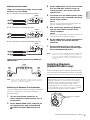
Connectors
• XLR-type connectors are wired as follows (IEC60268 standard):
pin 1: ground, pin 2: hot (+), and pin 3: cold (-).
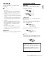
Connectable cables
XLR type
XLR type connectors are widely used in professional audio
equipment and installations. The XLR type connectors
provided on the HS series speakers are primarily intended for
use with balanced connections.
Phone type
Phone type connectors can be used for both unbalanced and
balanced connections.
Cables fitted with TRS (tip, ring, sleeve) phone plugs are
necessary for balanced connections to the HS series
speakers. The construction of TRS phone plugs is basically
the same as stereo phone plugs.
For unbalanced connections, connect standard mono phone
plug cables to the HS speaker phone connectors.
RCA pin
Source devices that only have RCA pin type output
connectors can be connected via RCA pin plug to phone plug
conversion cables (cables with an RCA pin plug on one end
and a phone plug on the other). Connections using RCA pin
plug to phone plug conversion cables are unbalanced.
Balanced connections: These effectively cancel
noise picked up from external sources. Balanced
connections allow for longer cable runs that would
probably otherwise result in more noise being picked up.
Unbalanced connections: Commonly used to
connect electronic musical instruments and guitars, etc.,
to amplification equipment. If your cable runs do not
extend past one or two meters, unbalanced cables can
probably be used without any problems.
Pin 2: hot (+)
Pin 3: cold (-)
Pin 1: ground
Pin 1: ground
Pin 3: cold (-)
Pin 2: hot (+)
Tip: hot (+)
Ring: cold (-)
Sleeve: ground
Tip: hot (+)
Sleeve: ground

HS8/HS7/HS5/HS8I/HS7I/HS5I/HS8S Owner’s Manual
6
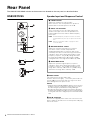
Rear Panel
The HS8/HS7/HS5/HS8S switches and connectors are located on the rear panel, as described below.
HS8/HS7/HS5
Speaker Input and Response Control
Power switch
Turns power to the speaker ON or OFF.
Rock the switch to the right [ ] to turn the power ON, or to
the left [ ] to turn the power OFF. The logo on the front
panel will light when the power is ON.
NOTICE
• Turning the power switch ON and OFF in rapid succession can cause
the device’s electronics to malfunction. Please wait for 3 seconds or
more after turning the power OFF before turning it ON again.
• Even when the power switch is turned off, electricity is still flowing to
the product at the minimum level. When you are not using the product
for a long time, make sure to unplug the power cord from the wall AC
outlet.
AC IN connector
Connect the supplied power cable here. First connect the
power cord to the speaker, then insert the power cord plug
into the AC outlet.
LEVEL control
Adjusts the output level of the speaker.
When set to the 12-o’clock position the speaker is
optimized for a nominal input level of +4 dB.
INPUT 1/2 connector
These connectors receive the input signal to the
speaker. Two input connectors are provided: one
balanced XLR connector, and one balanced (TRS)
phone jack.
NOTE The XLR and phone jack input connectors can not be
used simultaneously. Use only one input connector at a
time.
NOTE Refer to “Connectable cables” on page 5 for more
connector details.
ROOM CONTROL switch
Adjusts the speaker’s low-frequency response.
This switch can be used to compensate for
exaggerated low-frequency response that can be
caused by reflections in some listening environments.
Setting the switch to the [0] position produces a flat
frequency response. The [-2 dB] setting attenuates
the range below 500 Hz by 2 dB, and the [-4 dB]
setting attenuates the range below 500 Hz by -4 dB.
HIGH TRIM switch
Adjusts the speaker’s high-frequency response.
Setting the switch to the [0] position produces a flat
frequency response. The [+2 dB] setting boosts the
range above 2 kHz by 2 dB, while the [-2 dB] setting
attenuates the range above 2 kHz by -2 dB.

HS8/HS7/HS5/HS8I/HS7I/HS5I/HS8S Owner’s Manual
7
English
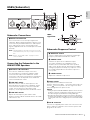
HS8S (Subwoofer)
Subwoofer Connections
Connecting the Subwoofer to the
HS8/HS7/HS5 Speakers
Subwoofer Response Control
Power switch
Turns power to the subwoofer ON or OFF.
Rock the switch to the right [ ] to turn the power ON, or to
the left [ ] to turn the power OFF. The logo on the front
panel will light when the power is ON.
NOTICE
• Turning the power switch ON and OFF in rapid succession can cause
the device’s electronics to malfunction. Please wait for 3 seconds or
more after turning the power OFF before turning it ON again.
• Even when the power switch is turned off, electricity is still flowing to
the product at the minimum level. When you are not using the product
for a long time, make sure to unplug the power cord from the wall AC
outlet.
AC IN connector
Connect the supplied power cable here. First connect the
power cord to the subwoofer, then insert the power cord
plug into the AC outlet.
INPUT L/R connector
These connectors receive the input signal to the
subwoofer. Balanced XLR and balanced phone jack
connectors are provided for both the L and R inputs.
The L and R inputs can be used simultaneously.
Signals supplied to both the L and R inputs are mixed
internally.
NOTE The XLR and phone jack input connectors can not be
used simultaneously. Use only one input connector at a
time.
NOTE Refer to “Connectable cables” on page 5 for more
connector details.
OUTPUT L/R connectors
These are the subwoofer’s output connectors.
The input signals received at the INPUT L and R
connectors are output via the OUTPUT L and R
connectors, respectively. Low frequency reproduction
characteristics can be adjusted via the LOW CUT
switch and LOW CUT control.
LOW CUT switch
When this switch is ON, the low frequencies are
attenuated prior to output via the OUTPUT L and R
connectors at the frequency set by the LOW CUT
control. The low-frequency attenuation cutoff
frequency can be adjusted via the LOW CUT control.
LOW CUT control
Adjusts the low-frequency attenuation cutoff
frequency between 80 Hz and 120 Hz when the LOW
CUT switch is ON.
HIGH CUT control
Sets the cutoff frequency for subwoofer output high-
frequency attenuation from 80 Hz to 120 Hz.
PHASE switch
Switches the phase of the subwoofer output.
This switch should be set to [NORM.] in most
situations, but in combination with some speakers
and in some speaker layouts switching to the [REV.]
setting may improve low-frequency response. Select
the setting that provides the best bass response in
your system.
LEVEL control
Adjusts the subwoofer output level.
HS8S
signal flow

HS8/HS7/HS5/HS8I/HS7I/HS5I/HS8S Owner’s Manual
8
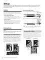
Setup
In this section we’ll look at the general procedure for connecting and setting up a monitor speaker system.
This is just an example though, so feel free to set up your own system in the way that best serves your
personal listening needs.
Cables
You’ll need to acquire appropriate cables to connect
the HS series monitor speakers to your audio interface
or other source equipment.
• Short, high-quality cables
Use high-quality cables of the shortest practical
length. The longer the cable, the more chance there
is that noise will creep in to degrade your sound.
• Balanced cables
Balanced cables are more resistant to noise than
unbalanced cables. If you have to use unbalanced
cables because the source equipment only has
unbalanced outputs, be sure to use the shortest
possible unbalanced cables.
Connections
NOTICE
Plug the supplied AC power cord into the corresponding socket on the
speaker. Plug the power cord into the speaker first, and then insert the
AC plug end into an appropriate AC wall outlet.
When connecting an audio interface (Steinberg UR or
AXR series, etc.) to HS series speakers, connect the
audio interface output connectors directly to the
speakers’ input connectors. Normally you’ll connect to
the LINE OUT 1 and 2 (1L and 2R outputs), although
that might depend on the specific audio interface and
DAW (Digital Audio Workstation) settings used.
Recommended cables
For connection to a balanced phone jack input.
For connection to an unbalanced phone jack input.
NOTE Refer to “Connectable cables” on page 5 for more connector
details. The configurations of the balanced and unbalanced
phone jack connectors are different.
When connecting a mixer (Yamaha MGP or MG series,
etc.) to HS series speakers, connect the mixer’s
MONITOR OUT or C-R OUT (Control Room) connectors
directly to the speakers’ input connectors. This makes it
possible to control the monitor level independently from
the mixer’s main bus level.
Connecting to an Audio Interface
HS8/HS7/HS5 HS8/HS7/HS5
Connecting to a Mixer
HS8/HS7/HS5
or
HS8/HS7/HS5
HS8/HS7/HS5 HS8/HS7/HS5
INPUT INPUT
MONITOR
OUT
or
C-R OUT
LR

HS8/HS7/HS5/HS8I/HS7I/HS5I/HS8S Owner’s Manual
9
English
Recommended cables
For connection to a balanced XLR input.
For connection to an unbalanced phone jack input.
NOTE Refer to “Connectable cables” on page 5 for more connector
details. The configurations of the balanced and unbalanced
phone jack connectors are different.
When connecting an electronic musical instrument
such as a Yamaha MONTAGE synthesizer to the HS
series speakers, connect the instrument’s L/MONO and
R outputs to the HS speaker inputs.
Recommended cables
For connection to an unbalanced phone jack input.
NOTE Refer to “Connectable cables” on page 5 for more connector
details. The configurations of the balanced and unbalanced
phone jack connectors are different.
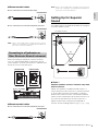
Setting Up for Superior
Sound
A number of points should be observed when laying out
a monitor speaker system.
Point 1
Position speakers at least 1.5 meters away from
walls or corners.
Ideally, the speakers should be located at least 1.5
meters away from walls or corners. In situations where it
is not possible to position the speakers a sufficient
distance from walls or corners, the ROOM CONTROL
switch can be used compensate for excessive bass. As
you move the speaker closer to walls or corners, a
higher compensation setting may be required to
achieve natural sounding response ([0] → [-2] → [-4]).
Connecting to a Synthesizer or
Other Electronic Musical Instrument
HS8/HS7/HS5
HS8/HS7/HS5
HS8/HS7/HS5 HS8/HS7/HS5
OUTPUT L/MONO OUTPUT R
HS8/HS7/HS5
60˚
1.5
meters
or more
1.5 meters or more

HS8/HS7/HS5/HS8I/HS7I/HS5I/HS8S Owner’s Manual
10
Point 2
Position the left and right speakers
symmetrically.
The left and right speakers should be positioned as
symmetrically as possible in relation to the room. In
other words, the left and right speakers should be the
same distance from the rear wall and the respective left
and right walls.
Point 3
The optimum listening position is at the apex of
an equilateral triangle.
For the most accurate sound and balance, position
yourself at the apex of an equilateral triangle formed by
the left and right speakers and yourself, with the
speakers angled inward so that they’re facing you.
Point 4
Position the tweeters at ear height.
High frequencies are quite directional, so for the most
accurate monitoring the speakers should be set up so
that the tweeters are at approximately the same height
as your ears when you’re seated at the listening
position.
HS8/HS7/HS5 Settings
Once the physical layout of your monitor system is
finalized, you can begin making the following settings.
1 Turn the level/volume controls on all
source equipment (audio interface, etc.) all
the way down.
2 Set the HS8/HS7/HS5 LEVEL control to the
12-o’clock position, and set both ROOM
CONTROL and HIGH TRIM switches to 0
dB.
3 Turn the power to connected audio source
devices on first, and then turn on power to
the speakers.
NOTICE
When turning power off, turn off the speakers first, and then turn
off connected audio source devices.
4 Play some source material and gradually
raise the level/volume controls on the
source equipment.
NOTICE
Be careful not to suddenly apply an excessively loud signal to the
system. Excessive level can damage the speakers.
5 Set the listening level to a level at which
you can listen comfortably without fatigue
for an extended period of time.
NOTE If necessary, adjust the ROOM CONTROL and HIGH TRIM
switches for the most natural response (refer to page 6).
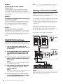
Adding a Subwoofer (HS8S)
Adding a subwoofer to your monitor system can
significantly improve its low-frequency fidelity, making it
possible to create better overall mixes.
The subwoofer is normally placed on the floor between
the left and right full-range speakers, but since the
subwoofer reproduces low frequencies below 200 Hz
that are relatively non-directional, subwoofer positioning
is not critical.
Four cables are required: two to connect the audio
interface or other source equipment to the HS8S
subwoofer, and two more to connect the subwoofer to
the left and right HS8/HS7/HS5 main speakers.
The connections are made as shown below.
NOTICE
Plug the supplied AC power cord into the corresponding socket on the
speaker. Plug the power cord into the speaker first, and then insert the
AC plug end into an appropriate AC wall outlet.
HS8S
HS8/HS7/HS5 HS8/HS7/HS5
HS8/HS7/HS5
HS8S
Audio interface or
other source

HS8/HS7/HS5/HS8I/HS7I/HS5I/HS8S Owner’s Manual
11
English
Recommended cables
Cables for connecting the audio source (audio
interface, etc.) to the HS8S
For connection to a balanced phone jack input.
For connection to a balanced XLR input.
For connection to an unbalanced phone jack input.
Cables for connection between the HS8S and
HS8/HS7/HS5
NOTE Refer to “Connectable cables” on page 5 for more connector
details. The configurations of the balanced and unbalanced
phone jack connectors are different.
Settings for Speakers Plus Subwoofer
Once the subwoofer connections have been made and
the layout is finalized, you can begin making the
following settings.
1 Turn the level/volume controls on all
source equipment (audio interface, etc.) all
the way down.
2 Set the HS8/HS7/HS5 LEVEL control to the
12-o’clock position, and set both ROOM
CONTROL and HIGH TRIM switches to 0
dB.
3 Set the HS8S LEVEL control to 0, the HIGH
CUT and LOW CUT controls to their 12-
o’clock positions, and set the LOW CUT
switch to OFF.
4 Turn power on in the following order: audio
source devices, then subwoofer, and finally
the full-range speakers.
NOTICE
Turn power off in the following order: full-range speakers, then
subwoofer, and finally audio source devices.
5 Play some source material and gradually
raise the level/volume controls on the
source equipment.
NOTICE
Be careful not to suddenly apply an excessively loud signal to the
system. Excessive level can damage the speakers.
6 Set the HS8S LEVEL control to between 10
and 12 o’clock, and turn the LOW CUT
switch ON.
7 Set the listening level to a level at which
you can listen comfortably without fatigue
for an extended period of time.
NOTE • If necessary, adjust the ROOM CONTROL and HIGH TRIM
switches for the most natural response (refer to page 6).
• If necessary, adjust the LOW CUT and HIGH CUT controls
and the PHASE switch for the most natural response (refer
to page 7).
Installing Brackets
(HS8I/HS7I/HS5I only)
HS8I/HS7I/HS5I can be installed with optional brackets.
Two screw holes for installing the brackets are located
on each of the four surfaces (top, bottom, left and right).
HS8S
HS8S
HS8S
HS8S
HS8
HS7
HS5
HS8
HS7
HS5
Refer also to the bracket installation manual.
Note that there are two sets of screws: those that are
originally installed in the speaker cabinet (to plug the
installation holes) and those (for bracket installation)
that are included in the product package. When
installing brackets to the speaker, remove the original
screws and make sure to use only the screws included
in the product package for bracket installation.
Screw holes for installing
brackets

HS8/HS7/HS5/HS8I/HS7I/HS5I/HS8S Owner’s Manual
12
Caution
• Construction work should be carried out by a professional
constructor.
• Do not install the speaker transversely.
• Make sure not to touch the cone when installing.
• For optimum safety, the installation should be checked thoroughly at
regular intervals. Some fittings may deteriorate over extended periods
of time due to wear and/or corrosion, or the mounted parts may
loosen.
• When choosing the installation location such as wall and ceiling and
mounting hardware (bolts, nuts), make sure all are strong enough to
support the weight of the speaker.
• Make sure to properly use the safety wire to prevent the speaker from
falling down in the event of an installation failure.
• When installing the safety wire to the ceiling or wall, install it higher
than the wire's attachment point on the speaker to reduce slack. Also,
ensure that the installation height and location would pose no danger
to people should the speaker fall.
• Yamaha does not assume any responsibilities for accidents such as
dropping due to insufficient strength at attachment points or
inadequacy of the mounting method.
• The recommended tightening torque for installing the included screws
for bracket installation is 6.2 Nm for the M8 screw (HS8I and HS7I)
and 2.4 Nm for the M5 screw (HS5I).
• Use safety wires with the following specifications.
NOTE Do not use the speaker if the screws at locations where
brackets are not installed have been removed. This causes air
leaks to occur from the enclosure, resulting in undesirable
performance.
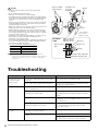
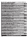
Troubleshooting
Diameter Ø3.0 mm or more
Length Less than 600 mm
Material Stainless steel
Breaking load 6,370 N (650 kg) or more
Sectional
view
Eyenut
Screws included
with the product
Included screws
for bracket
installation
Safety
wire
Eyebolt
HS8I: 25–50 mm
HS7I: 25–30 mm
HS5I: 20–25 mm
Enclosure
Washer, etc.
Eyebolt
HS8I/HS7I: Ø18, HS5I: Ø12
HS8I/HS7I: M8, HS5I: M5
Reinforcement
plate
* This example
shows how to
install to a wall.
Symptom Possible Cause Solution
Power won’t turn on /
front panel logo
doesn’t light.
The power cord might not be connected
properly.
Check and connect the power cord.
The power switch might not be turned on. Turn the power switch ON. If the problem persists,
contact your Yamaha dealer.
No sound. One or more cables might not be
connected properly.
Check that all cables are properly connected.
The source equipment might not be
supplying an audio signal.
Make sure that the source equipment is
functioning properly and delivering the required
signal.
The level setting might be too low. Adjust the output level setting of the source
equipment, or use the LEVEL control to increase
the output level.
Are cables connected to both the XLR and
phone jack INPUT connectors?
The XLR and phone jack input connectors can not
be used simultaneously. Use only one input
connector at a time.
Noisy or distorted
sound.
One or more cables might be corroded,
shorted, or otherwise broken.
Replace faulty cable(s).
The system might be picking up external
noise.
Try changing the positions or layout of the cables.
Try changing the location of other electrical/
electronic devices that are near the speakers.

87
EnglishDeutschFrançaisEspañolPortuguêsItalianoРусский
Information for users on collection and disposal of old
equipment:
This symbol on the products, packaging, and/or accompanying
documents means that used electrical and electronic products
should not be mixed with general household waste.
For proper treatment, recovery and recycling of old products,
please take them to applicable collection points, in accordance
with your national legislation.
By disposing of these products correctly, you will help to save
valuable resources and prevent any potential negative effects on
human health and the environment which could otherwise arise from
inappropriate waste handling.
For more information about collection and recycling of old products, please
contact your local municipality, your waste disposal service or the point of sale
where you purchased the items.
For business users in the European Union:
If you wish to discard electrical and electronic equipment, please contact your
dealer or supplier for further information.
Information on Disposal in other Countries outside the European Union:
This symbol is only valid in the European Union. If you wish to discard these
items, please contact your local authorities or dealer and ask for the correct
method of disposal.
(weee_eu_en_02)
Verbraucherinformation zur Sammlung und Entsorgung
alter Elektrogeräte
Befindet sich dieses Symbol auf den Produkten, der Verpackung
und/oder beiliegenden Unterlagen, so sollten benutzte
elektrische Geräte nicht mit dem normalen Haushaltsabfall
entsorgt werden.
In Übereinstimmung mit Ihren nationalen Bestimmungen bringen
Sie alte Geräte bitte zur fachgerechten Entsorgung,
Wiederaufbereitung und Wiederverwendung zu den
entsprechenden Sammelstellen.
Durch die fachgerechte Entsorgung der Elektrogeräte helfen Sie, wertvolle
Ressourcen zu schützen, und verhindern mögliche negative Auswirkungen auf
die menschliche Gesundheit und die Umwelt, die andernfalls durch
unsachgerechte Müllentsorgung auftreten könnten.
Für weitere Informationen zum Sammeln und Wiederaufbereiten alter
Elektrogeräte kontaktieren Sie bitte Ihre örtliche Stadt- oder Gemeindeverwaltung,
Ihren Abfallentsorgungsdienst oder die Verkaufsstelle der Artikel.
Information für geschäftliche Anwender in der Europäischen Union:
Wenn Sie Elektrogeräte ausrangieren möchten, kontaktieren Sie bitte Ihren
Händler oder Zulieferer für weitere Informationen.
Entsorgungsinformation für Länder außerhalb der Europäischen Union:
Dieses Symbol gilt nur innerhalb der Europäischen Union. Wenn Sie solche Artikel
ausrangieren möchten, kontaktieren Sie bitte Ihre örtlichen Behörden oder Ihren
Händler und fragen Sie nach der sachgerechten Entsorgungsmethode.
(weee_eu_de_02)
Informations concernant la collecte et le traitement des
déchets d’équipements électriques et électroniques
Le symbole sur les produits, l'emballage et/ou les documents
joints signifie que les produits électriques ou électroniques
usagés ne doivent pas être mélangés avec les déchets
domestiques habituels.
Pour un traitement, une récupération et un recyclage appropriés
des déchets d’équipements électriques et électroniques, veuillez
les déposer aux points de collecte prévus à cet effet,
conformément à la réglementation nationale.
En vous débarrassant correctement des déchets d’équipements électriques et
électroniques, vous contribuerez à la sauvegarde de précieuses ressources et à
la prévention de potentiels effets négatifs sur la santé humaine qui pourraient
advenir lors d'un traitement inapproprié des déchets.
Pour plus d'informations à propos de la collecte et du recyclage des déchets
d’équipements électriques et électroniques, veuillez contacter votre municipalité,
votre service de traitement des déchets ou le point de vente où vous avez
acheté les produits.
Pour les professionnels dans l'Union européenne :
Si vous souhaitez vous débarrasser des déchets d’équipements électriques et
électroniques, veuillez contacter votre vendeur ou fournisseur pour plus
d'informations.
Informations sur la mise au rebut dans d'autres pays en dehors de l'Union
européenne :
Ce symbole est seulement valable dans l'Union européenne. Si vous souhaitez
vous débarrasser de déchets d’équipements électriques et électroniques,
veuillez contacter les autorités locales ou votre fournisseur et demander la
méthode de traitement appropriée.
(weee_eu_fr_02)
Información para usuarios sobre la recogida y
eliminación de los equipos antiguos
Este símbolo en los productos, embalajes y documentos anexos
significa que los productos eléctricos y electrónicos no deben
mezclarse con los desperdicios domésticos normales.
Para el tratamiento, recuperación y reciclaje apropiados de los
productos antiguos, llévelos a puntos de reciclaje
correspondientes, de acuerdo con la legislación nacional.
Al deshacerse de estos productos de forma correcta, ayudará a
ahorrar recursos valiosos y a impedir los posibles efectos
desfavorables en la salud humana y en el entorno que de otro modo se
producirían si se trataran los desperdicios de modo inapropiado.
Para obtener más información acerca de la recogida y el reciclaje de los
productos antiguos, póngase en contacto con las autoridades locales, con el
servicio de eliminación de basuras o con el punto de venta donde adquirió los
artículos.
Para los usuarios empresariales de la Unión Europea:
Si desea desechar equipos eléctricos y electrónicos, póngase en contacto con
su vendedor o proveedor para obtener más información.
Información sobre la eliminación en otros países fuera de la Unión Europea:
Este símbolo solo es válido en la Unión Europea. Si desea desechar estos
artículos, póngase en contacto con las autoridades locales o con el vendedor y
pregúnteles el método correcto.
(weee_eu_es_02)
Informazioni per gli utenti sulla raccolta e lo smaltimento
di vecchia attrezzatura
Questi simboli sui prodotti, sull'imballaggio e/o sui documenti che
li accompagnano, indicano che i prodotti elettrici ed elettronici
non devono essere mischiati con i rifiuti generici.
Per il trattamento, il recupero e il riciclaggio appropriato di vecchi
prodotti, si prega di portarli ai punti di raccolta designati, in
accordo con la legislazione locale.
Smaltendo correttamente questi prodotti si potranno recuperare
risorse preziose, oltre a prevenire potenziali effetti negativi sulla
salute e l'ambiente che potrebbero sorgere a causa del trattamento improprio dei
rifiuti.
Per ulteriori informazioni sulla raccolta e il riciclaggio di vecchi prodotti, si prega
di contattare l’amministrazione comunale locale, il servizio di smaltimento dei
rifiuti o il punto vendita dove sono stati acquistati gli articoli.
Per utenti imprenditori dell'Unione europea:
Se si desidera scartare attrezzatura elettrica ed elettronica, si prega di contattare
il proprio rivenditore o il proprio fornitore per ulteriori informazioni.
Informazioni sullo smaltimento negli altri Paesi al di fuori dell'Unione
europea:
Questi simboli sono validi solamente nell'Unione Europea; se si desidera
scartare questi articoli, si prega di contattare le autorità locali o il rivenditore e
richiedere informazioni sulla corretta modalità di smaltimento.
(weee_eu_it_02)
Informações para os utilizadores relativas à recolha e
eliminação de equipamentos usados
Este símbolo, presente em produtos, embalagens e/ou incluído
na documentação associada, indica que os produtos elétricos e
eletrónicos usados não devem ser eliminados juntamente com
os resíduos domésticos em geral.
O procedimento correto consiste no tratamento, recuperação e
reciclagem de produtos usados, pelo que deve proceder à
respetiva entrega nos pontos de recolha adequados, em
conformidade com a legislação nacional em vigor.
A eliminação destes produtos de forma adequada permite poupar recursos
valiosos e evitar potenciais efeitos prejudiciais para a saúde pública e para o
ambiente, associados ao processamento incorreto dos resíduos.
Para mais informações relativas à recolha e reciclagem de produtos usados,
contacte as autoridades locais, o serviço de eliminação de resíduos ou o ponto
de venda onde foram adquiridos os itens relevantes.
Informações para utilizadores empresariais na União Europeia:
Para proceder à eliminação de equipamento elétrico e eletrónico, contacte o seu
revendedor ou fornecedor para obter informações adicionais.
Informações relativas à eliminação em países não pertencentes à União
Europeia:
Este símbolo é válido exclusivamente na União Europeia. Caso pretenda eliminar
este tipo de itens, contacte as autoridades locais ou o seu revendedor e informe-
se acerca do procedimento correto para proceder à respetiva eliminação.
(weee_eu_pt_02a)

88
* The contents of this manual apply to the latest specifications as of the publishing date. To obtain the latest manual, access the
Yamaha website then download the manual file. Since specifications, equipment or separately sold accessories may not be the
same in every locale, please check with your Yamaha dealer.
* Der Inhalt dieser Bedienungsanleitung gilt für die neuesten technischen Daten zum Zeitpunkt der Veröffentlichung. Um die neueste
Version der Anleitung zu erhalten, rufen Sie die Website von Yamaha auf und laden Sie dann die Datei mit der
Bedienungsanleitung herunter. Da die Technischen Daten, das Gerät selbst oder gesondert erhältliches Zubehör nicht in jedem
Land gleich sind, setzen Sie sich im Zweifel bitte mit Ihrem Yamaha-Händler in Verbindung.
* Le contenu de ce mode d’emploi s’applique aux dernières caractéristiques techniques connues à la date de publication du manuel.
Pour obtenir la version la plus récente du manuel, accédez au site Web de Yamaha puis téléchargez le fichier du manuel concerné.
Étant donné que les caractéristiques techniques, les équipements et les accessoires vendus séparément varient d’un pays à
l’autre, adressez-vous pour cela à votre distributeur Yamaha.
* El contenido de este manual se aplica a las últimas especificaciones según la fecha de publicación. Para obtener el último manual,
acceda al sitio web de Yamaha y descargue el archivo del manual. Puesto que las especificaciones, los equipos o los accesorios
que se vendan aparte podrían no ser iguales en todos los sitios, consulte al distribuidor de Yamaha.
* O conteúdo deste manual se aplica às especificações mais recentes a partir da data de publicação. Para obter o manual mais
recente, acesse o site da Yamaha e faça o download do arquivo do manual. Como as especificações, os equipamentos ou os
acessórios vendidos separadamente podem não ser iguais em todas as localidades; consulte o revendedor Yamaha.
* Il contenuto del presente manuale si applica alle ultime specifiche tecniche a partire dalla data di pubblicazione. Per ottenere la
versione più recente del manuale, accedere al sito Web Yamaha e scaricare il file corrispondente. Dal momento che le specifiche
tecniche, le apparecchiature e gli accessori venduti separatamente potrebbero variare a seconda del paese in cui viene distribuito il
prodotto, verificarli con il rivenditore Yamaha.
* В содержании данного руководства приведены последние на момент публикации технические характеристики. Для
получения последней версии руководства посетите веб-сайт корпорации Yamaha и загрузите файл с руководством. Так как
технические характеристики, оборудование и отдельно продаваемые принадлежности могут различаться в разных
стра
нах,
обратитесь за информацией к представителю корпорации Yamaha в своем регионе.
이 기기는 가정용(B급) 전자파적합기기로서 주로
가정에서 사용하는 것을 목적으로 하며, 모든
지역에서 사용할 수 있습니다.
(class b korea)

89
EnglishDeutschFrançaisEspañolPortuguêsItalianoРусский
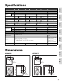
Specifications
Dimensions
HS8/HS8I HS7/HS7I
Model HS8 HS8I HS7 HS7I HS5 HS5I HS8S
General Specifications
Type Bi-amp 2-way powered speaker Powered subwoofer
Crossover Frequency 2 kHz –
Overall
Frequency
Response
-3dB 47 Hz – 24 kHz 55 Hz – 24 kHz 74 Hz – 24 kHz 33 Hz – 124 Hz
-10dB 38 Hz – 30 kHz 43 Hz – 30 kHz 54 Hz – 30 kHz 22 Hz – 160 Hz
Mounting Points –
Four surfaces x 2 x M8
(120 mm pitch)
–
Four surfaces x 2 x M8
(120 mm pitch)
–
Four surfaces x 2 x M5
(60 mm pitch)
–
Dimensions (W x H x D)
250 x 390 x 334 mm
9-13/16 x 15-3/8 x 13-1/8"
210 x 332 x 284 mm
8-1/4 x 13-1/16 x 11-3/16"
170 x 285 x 222 mm
6-11/16 x 11-1/4 x 8-3/4"
300 x 350 x 389 mm
11-13/16 x 13-3/4 x 15-5/16"
Weight
10.2 kg
(22.5 lb.)
10.7 kg
(23.6 lb.)
8.2 kg
(18.1 lb.)
8.7 kg
(19.2 lb.)
5.3 kg
(11.7 lb.)
5.5 kg
(12.1 lb.)
12.5 kg (27.6 lb.)
Speaker Components
Speaker Components
LF: 8" cone
HF: 1" dome
LF: 6.5" cone
HF: 1" dome
LF: 5" cone
HF: 1" dome
8" cone
Enclosure Bass-reflex type, Material: MDF
Amplifier Unit
Output Power
Total 120 W (dynamic power) 95 W (dynamic power) 70 W (dynamic power)
150 W, 4 ohms (dynamic
power)
LF 75 W (4 ohms) 60 W (4 ohms) 45 W (4 ohms) –
HF 45 W (8 ohms) 35 W (8 ohms) 25 W (8 ohms) –
Input Sensitivity / Impedance
-10 dBu/10k ohms
Output Level/Impedance – -10 dBu/600 ohms
Input Connectors (Parallel)
1: XLR-3-31 type (balanced)
2: PHONE (balanced)
Output Connectors –
XLR-3-32 type (balanced) x2
(L&R)
Controls
LEVEL control (+4 dB, center click)
EQ: HIGH TRIM switch (+/- 2 dB at HF),
ROOM CONTROL switch (0/-2/-4 dB under 500Hz)
LEVEL control
PHASE switch (NORM./REV.)
HIGH CUT control
(80 – 120 Hz, center click)
LOW CUT control
(80 – 120 Hz, center click)
LOW CUT switch (ON/OFF)
Indicator Power ON (White LED)
Power Consumption 60 W 55 W 45 W 70 W
250 (9-13/16")
390 (15-3/8")
334 (13-1/8")
120
2-M8
(HS8I Only)
75
2975
120 150
2-M8
(HS8I Only)
Unit: mm (inch)
210 (8-1/4")
332 (13-1/16")
284 (11-3/16")
2-M8
(HS7I only)
2-M8
(HS7I only)
120
75
75 29
120 120
Unit: mm (inch)

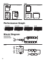
90
HS5/HS5I HS8S
Performance Graph
Block Diagram
170 (6-11/16")
285 (11-1/4")
222 (8-3/4")
2-M5
(HS5I only)
2-M5
(HS5I only)
60
44
97 17
11060
Unit: mm (inch)
300 (11-13/16") 389 (15-5/16")
350 (13-3/4")
Unit: mm (inch)
HS8/HS8I HS7/HS7I HS5/HS5I HS8S
INPUT 1
HIGH CUT
LIMITER
HIGH TRIM
INPUT 2
LF
HF
LEVEL
LOW CUT
ROOM CONTROL
LOW BOOST STEP FILTER
P. A M P
STEP FILTER LOWCUT P.AMP
INPUT
OUTPUT
LOW CUT
OUTPUT
R ch L ch
LOW CUT ON/OFF
SUM
SPEAKER
PHASE
NORMAL
REVERSE
LEVEL
P. A M P
INPUT
INPUT
INPUT
LOW CUT
HIGH CUT
LIMITTER
HS8/HS7/HS5
HS8I/HS7I/HS5I
HS8S

91
EnglishDeutschFrançaisEspañolPortuguêsItalianoРусский
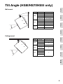
Tilt Angle (HS8I/HS7I/HS5I only)
Wall mount
Ceiling mount
Model Bracket Maximum tilt angle
HS8I
BWS251-300 30°
BWS251-400 45°
BWS50-260 0°
BWS50-190 Not compatible
HS7I
BWS251-300 35°
BWS251-400 45°
BWS50-260 0°
BWS50-190 Not compatible
HS5I
BWS20-190 0°
BWS20-120 Not compatible
Model Bracket Maximum tilt angle
HS8I
BCS251 45°
BWS50-260
30°
BWS50-190
HS7I
BCS251 45°
BWS50-260
30°
BWS50-190
HS5I
BCS20-210
20°
BCS20-150
BWS20-190
BWS20-120


Yamaha Pro Audio global website
http://www.yamahaproaudio.com/
Yamaha Downloads
https://download.yamaha.com/
VDV6540
Manual Development Group
© 2016 Yamaha Corporation
Published 01/2020
MWEI-C0
-
 1
1
-
 2
2
-
 3
3
-
 4
4
-
 5
5
-
 6
6
-
 7
7
-
 8
8
-
 9
9
-
 10
10
-
 11
11
-
 12
12
-
 13
13
-
 14
14
-
 15
15
-
 16
16
-
 17
17
-
 18
18
-
 19
19
-
 20
20


Yamaha HS5 Instrukcja obsługi
- Kategoria
- Dodatkowy sprzęt muzyczny
- Typ
- Instrukcja obsługi
w innych językach
- čeština: Yamaha HS5 Návod k obsluze
- español: Yamaha HS5 El manual del propietario
- italiano: Yamaha HS5 Manuale del proprietario
- Deutsch: Yamaha HS5 Bedienungsanleitung
- português: Yamaha HS5 Manual do proprietário
- français: Yamaha HS5 Le manuel du propriétaire
- English: Yamaha HS5 Owner's manual
- dansk: Yamaha HS5 Brugervejledning
- Nederlands: Yamaha HS5 de handleiding
- română: Yamaha HS5 Manualul proprietarului
Powiązane artykuły
-
Yamaha Powered Speaker System MSP3A Instrukcja obsługi
-
Yamaha MSP3A Instrukcja obsługi
-
Yamaha MSP10STUDIO Instrukcja obsługi
-
-
-
-
Yamaha TRS-MS05 Instrukcja obsługi
-
Yamaha MSP5 STUDIO Instrukcja obsługi
-
-