
PIANO DI COTTURA
BUILT-IN HOB
ВАРОЧНАЯ ПОВЕРХНОСТЬ
ВАРИЛЬНА ПОВЕРХНЯ
PŁYTA DO ZABUDOWY
Istruzioni per l`uso
User manual
Руководство пользователя
Керівництво з експлуатації
Instrukcja obsługi
HF640G, HF640GT, HF640VGT

IT
Grazie per aver acquistato un piano cottura della nostra società Freggia.
Si prega di leggere attentamente il presente libretto istruzioni, in quanto fornisce
importanti indicazioniriguardanti la sicurezza di installazione, d`uso e di manutenzione
del piano di cottura.
Conservarlo per ogni ulteriore consultazione.
EN
Thank you for purchasing Freggia built-in hob.
Please carefully read the user manual, as it contains the instructions for the safe
installation, operation and maintenance of the built-in hob.
Save it for future use.
RU
Freggia. -
, ,
,
.
.
UA
, Freggia. ,
, -
, .
.
PL
Dziękujemy Państwu za dokonanie zakupu płyty do zabudowy marki Freggia.
Prosimy o uważne zapoznanie się z instrukcją obsługi, gdyż zawiera ona wskazówki
dotyczące bezpiecznej instalacji, eksploatacji i obsługi płyty.
Zalecamy zachowanie jej do wykorzystania w przyszłości, jak również zapisanie nazwy
modelu i numeru seryjnego Państwa urządzenia.

IT
3
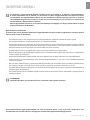
AVVERTENZE GENERALI
La invitiamo a leggere questo libretto istruzioni prima di installare e di utilizzare l’apparecchiatura.
E’ molto importante che il libretto sia conservato assieme all’apparecchiatura per qualsiasi futura
consultazione. Se l’apparecchiatura dovesse essere venduta o trasferita ad un’altra persona, assicurarsi
che il libretto venga fornito assieme, in modo che il nuovo utente possa essere messo al corrente del
funzionamento e delle relative avvertenze.
Questo apparecchio è di classe 3 ed è stato concepito per un impiego non di tipo professionale da parte
di privati all’interno di abitazioni.
Dichiarazione di conformità:
Si dichiara che i nostri prodotti soddisfano le vigenti direttive europee, ordini o regolamenti, nonché i requisiti
indicati nelle norme di riferimento.
• L’installazione deve essere eseguita da personale competente e quali cato secondo le norme vigenti.
• Quest’apparecchiatura è stata progettata per essere utilizzata da adulti.
• Questo apparecchio non è destinato all’ uso da parte di persone (inclusi i bambini) con ridotte capacità psichiche
o motorie, o con mancanza di esperienza e conoscenza, a meno che ci sia una supervisione o istruzione sull’ uso
dell’ apparecchio da parte di una persona responsabile per la loro sicurezza.
• I bambini devono essere sorvegliati per assicurarsi che non giochino con l’ apparecchio.
• Prima di alimentare l’apparecchiatura controllare che sia correttamente regolata per il tipo di gas a disposizione
(vedi paragrafo “installazione”)
• Prima della manutenzione o della pulizia disinserire elettricamente l’apparecchiatura e lasciarla ra reddare.
• Assicurarsi che ci sia una circolazione d’aria attorno all’apparecchiatura a gas. Una scarsa ventilazione produce
carenza di ossigeno.
• Nel caso di un utilizzo intenso o prolungato dell’apparecchio può necessitare di una areazione supplementare,
per esempio l’apertura di una nestra o aumentando la potenza di aspirazione meccanica se esiste.
• I prodotti della combustione devono essere scaricati all’esterno attraverso una cappa aspirante o elettroventilatore
(vedi paragrafo “installazione”).
• Per eventuali interventi o modi che rivolgersi ad un Centro di Assistenza Tecnica autorizzato ed esigere parti di
ricambio originali.
ATTENZIONE:
L’etichetta prodotto, con il numero di serie, è incollata sotto il piano di cottura.
Il costruttore declina ogni responsabilità nel caso di eventuali danni a cose o persone, derivanti da una
installazione non corretta o da un uso improprio, erroneo od irragionevole dell’apparecchio.
AVVERTENZE GENERALI

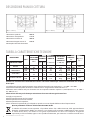
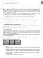
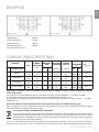
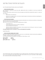
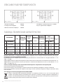
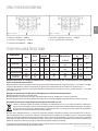
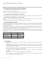
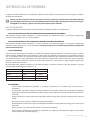
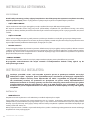
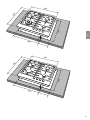
4DESCRIZIONE PIANI DI COTTURA
1 Bruciatore rapido di 3000 W
2 Bruciatore semirapido di 1750 W
3 Bruciatore ausiliario di 1000 W
5 Bruciatore doppia corona di 3500 W
8 Manopola comando bruciatore
Titolo breve o riferimento ai metodi di misurazione e di calcolo utilizzati per stabilire la conformità con i requisiti
di cui sopra.
La performance di ogni singolo bruciatore viene calcolata secondo la norma EN 30-2-1 + A1: 2003 + A2: 2005.
Il rendimento totale del piano di cottura è calcolato in base al regolamento UE 66/2014 Par. 2.2.
L’e cienza viene calcolata solo per i bruciatori con una capacità nominale superiore 1,16 KW (EN 30-2-1 + A1: 2003 +
A2:. 2005; Par 4.1)
Informazioni rilevanti per il cliente per minimizzare il consumo di energia durante l’uso.
Consigli per risparmiare:
utilizzare pentole comuni con base piana,
utilizzare pentole con il formato corretto,
utilizzare pentole con il coperchio,
ridurre al minimo la quantità di grasso liquido o, quando si avvia un liquido bollente ridurre l’impostazione.
Questo prodotto è conforme alla Direttiva EU 2002/96/EC.
Il simbolo del cestino barrato riportato sul prodotto indica che i Ri uti derivanti dalle Apparecchiature
Elettriche ed Elettroniche (RAEE) non devono essere buttati nella spazzatura indi erenziata (cioè insieme
ai “ri uti urbani misti”), ma devono essere gestiti separatamente così da essere sottoposti ad apposite
operazioni per il loro riutilizzo, oppure a uno speci co trattamento, per rimuovere e smaltire in modo sicuro
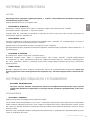
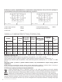
DESCRIZIONE PIANI DI COTTURA
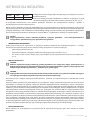
BRUCIATORI
GAS
PRESSIONE
ESERCIZIO
mbar
PORTATA
TERMICA
DIAMETRO
UGELLO
1/100 mm
DIAMETRO
BY PASS
RUBINETTI
1/100 mm
PORTATA
TERMICA
(W) EEgas burner
(%) *
N° DENOMINAZIONE g/h L/h Max.Min.
1 RAPIDO G30/G31
G20
28-30 / 37
20
218
-
-
286
85
115Y
42
Reg.
3000
3000
950
950 56.7
2 SEMIRAPIDO G30/G31
G20
28-30 / 37
20
127
-
-
167
65
97Z
31
Reg.
1750
1750
600
600 57
3 AUSILIARIO G30/G31
G20
28-30 / 37
20
73
-
-
95
50
72X
27
Reg.
1000
1000
450
450 /
5 DOPPIA CORONA G30/G31
G20
28-30 / 37
20
255
-
-
334
93
135
60
Reg.
3500
3500
2100
2100 58.1
TABELLA CARATTERISTICHE TECNICHE
(EEgas hob = 56.9 %) (EEgas hob = 57.4 %)

le eventuali sostanze dannose per l’ambiente ed estrarre le materie prime che possono essere riciclate. In Italia i RAEE
devono perciò essere consegnati ai Centri di Raccolta (chiamati anche isole ecologiche o piattaforme ecologiche)
allestiti dai Comuni o dalle Società di igiene urbana. Quando si acquista una nuova apparecchiatura, inoltre, si può
consegnare il RAEE al negoziante, che è tenuto a ritirarlo gratuitamente (ritiro “uno contro uno”); i RAEE di “piccolissime
dimensioni” (nei quali cioè nessuna dimensione supera i 25 cm) possono essere consegnati gratuitamente ai
negozianti anche quando non si compra nulla (ritiro “uno contro zero” – che però è obbligatorio solo per i negozi con
super cie di vendita superiore a 400 mq).
È necessario che tutte le operazioni relative all’installazione, alla regolazione, all’adattamento al tipo
gas disponibile, vengano eseguite da personale quali cato, secondo le norme in vigore.
Le istruzioni speci che sono descritte nella parte del libretto riservate all’installatore.
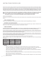
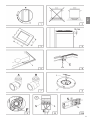
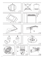
USO DEI BRUCIATORI
La simbologia serigrafata a lato delle manopole, indica la corrispondenza t ra manopola e bruciatore.
• ACCENSIONE AUTOMATICA SENZA VALVOLATURA
Ruotare in senso ant iorario la manopola corrispondente no alla posizione di massimo ( amma grande g. 1) e
premere la manopola.
• ACCENSIONE AUTOMATICA CON VALVOLATURA
Ruotare in senso ant iorario la manopola corrispondente no alla posizione di massimo ( amma grande g. 1) e
premere la manopola.
Ad accensione avvenuta mantenere premuta la manopola per circa 6 secondi.
• USO DEI BRUCIATORI
Per ottenere il massimo della resa senza spreco di gas è importante che il diametro della pentola sia adeguato alla
potenzialità del bruciatore (vedi tabella seguente), in modo da evitare che la amma esca dal fondo della pentola ( g.2).
Utilizzare la port at a massima per port are rapidamente in ebollizione i liquidi e quella ridotta per riscaldare le
vivande o per il mantenimento dell’ebollizione.
Tutte le posizioni di funzionamento devono essere scelte tra quelle di massimo e quella di minimo, mai tra la posizione
di massimo e il punto di chiusura.
Per interrompere l’alimentazione gas, ruotare la manopola in senso orario sulla posizione di chiusura.
In mancanza di energia elettrica è possibile accendere i bruciatori con i ammiferi posizionando la manopola al punto
di accensione ( amma grande g. 1).
• AVVERTENZE
• Controllare sempre che le manopole siano nella posizione di chiuso (vedi g.1) quando l’apparecchiatura
non è in funzione.
• In caso di spegnimento accidentale della amma, la valvola di sicurezza, dopo qualche secondo, interromperà
automaticamente l’erogazione del gas. Per ripristinare il funzionamento riportare la manopola al punto di
accensione ( amma grande g. 1) e premere.
• Durante la cottura con grassi o olii, porre la massima attenzione in quanto gli stessi, surriscaldandosi,
possono in ammarsi.
• Non utilizzare spray vicino all’apparecchio in funzione.
IT
5
ISTRUZIONI PER L’UTENTE
ISTRUZIONI PER L’UTENTE
Bruciatori potenze (W) Ø pentole
Ausiliario 1000 10 - 14 cm
Semirapido 1750 16 - 18 cm
Rapido 3000 20 - 22 cm
Doppia Corona 3500 24 - 26 cm

• Non devono essere poste sul bruciatore pentole instabili o deformate per evitare incidenti di rovesciamento
o trabocco.
• Assicurarsi che le maniglie delle pentole siano posizionate correttamente.
• Quando si accende il bruciatore controllare che la amma sia regolare, abbassare sempre la amma o
spegnerla prima di togliere le pentole.
• Quando si accende il bruciatore controllare che la amma sia regolare, abbassare sempre la amma o
spegnerla prima di togliere le pentole.
PULIZIA
Prima di ogni operazione scollegare l’apparecchio dalla rete di alimentazione elettrica. Non utilizzare pulitori a vapore
per la pulizia dell’apparecchio.
Si consiglia di operare ad apparecchio freddo.
• PARTI SMALTATE
Le parti smaltate devono essere lavate con una spugna ed acqua saponata o con detersivo leggero. Non usare prodotti
abrasivi o corrosivi.
Evitate che sostanze come succo di limone, pom odoro, acqua salina, acet o, c a è e lat t e rimangano a lungo
sulle super ci smaltate.
• PARTI IN ACCIAIO INOX
L’acciaio inox può rimanere macchiato se lasciato a contatto per lungo tempo con acqua calcarea o detergenti
aggressivi.
Si consiglia di lavare con acqua saponata e asciugare con panno morbido.
La lucentezza viene mantenuta mediante l’uso periodico di prodotti chimici idonei, reperibili in commercio.
• BRUCIATORI E GRIGLIE
Questi pezzi possono essere tolti per facilitare la pulizia.
I bruciatori devono essere lavati con una spugna ed acqua saponata o con detersivo leggero, ben asciugati e rimessi
perfettamente nel loro alloggiamento.
Controllare che i canali sparti amma non siano ostruiti.
Veri care che la sonda della valvola di sicurezza e l’elettrodo di accensione siano sempre ben puliti per garantire un
funzionamento ottimale.
• RUBINETTI A GAS
L’eventuale lubri cazione dei rubinetti deve essere eseguita esclusivamente da personale specializzato.
In caso di indurimento o di anomalie di funzionamento dei rubinetti gas chiamare il Servizio di Assistenza.
ISTRUZIONI PER L’INSTALLATORE
AVVERTENZA IMPORTANTE:
LE OPERAZIONI DI SEGUITO RIPORTATE DEVONO ESSERE ESEGUITE, NEL RISPETTO DELLE NORME
VIGENTI, ESCLUSIVAMENTE DA PERSONALE QUALIFICATO.
LA DITTA COSTRUTTRICE DECLINA OGNI RESPONSABILITÀ PER DANNI A PERSONE ANIMALI O COSE
DERIVANTI DALL’INNOSSERVANZA DI TALI DISPOSIZIONI.
6ISTRUZIONI PER L’INSTALLATORE
ISTRUZIONI PER L’UTENTE

IT
7
ISTRUZIONI PER L’INSTALLATORE
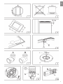
INSTALLAZIONE
• MONTAGGIO DEL PIANO
L’apparecchio è costruito per essere incassato in mobili resistenti al calore.
Le pareti dei mobili devono resistere ad una temperatura di 75°C oltre a quella ambientale secondo le normative
europee.
L’apparecchio è di tipo “ Y “, ovvero può essere installato con una sola parete laterale a destra o a sinistra del piano
cottura.
Evitare l’installazione dell’apparecchiatura in prossimità di materiali in ammabili come tendaggi, canevacci, ecc.
P r at icare un’aper t ur a nel piano del mobile delle dimensioni indicate nella g.3 rispettando una distanza di
almeno 50 mm dal bordo dell’apparecchio alle pareti adiacenti.
L’eventuale presenza di un pensile al di sopra del piano cottura deve
prevedere una distanza minima dal top di 760 mm.
Si consiglia di isolare l’apparecchio dal mobile sottostante con un
separatore lasciando uno spazio di depressione di almeno 10 mm. ( g. 4).
Nel caso di inserimento su base con forno è necessario prendere opportune precauzioni al ne di assicurare
un’installazione conforme alle norme antinfortunistiche. Si presti particolare attenzione a che il cavo elettrico ed il tubo
di alimentazione siano posizionati in modo da non venire a contatto con le parti calde dell’involucro del forno. Inoltre,
nel caso di installazione sopra un forno senza ventilazione forzata di ra reddamento, per consentire un’adeguata
aerazione dovranno essere previste delle opportune prese d’aria con super cie di entrata inferiore di almeno 200 cm2
e super cie di uscita superiore di almeno 60 cm2.
• FISSAGGIO DEL PIANO
Ogni piano di cottura viene corredato di una speciale guarnizione.
Viene inoltre fornita una serie di ganci da utilizzare per il ssaggio del piano. Per l’installazione procedere come segue:
• Togliere dal piano griglie e bruciatori.
• Rovesciare l’apparecchio e stendere lungo il bordo esterno la guarnizione S ( g. 5).
• Inserire e posizionare il piano cottura nell’apertura praticata nel mobile e bloccarlo con le viti V dei ganci
di ssaggio G ( g.6).
• LOCALE DI INSTALLAZIONE
Questo apparecchio non è provvisto di un dispositivo di scarico dei prodotti della combustione, è necessario quindi
scaricare questi fumi all’esterno utilizzando una cappa o un elettroventilatore che entri in funzione ogni volta che si
utilizza l’apparecchio.
Il locale dove viene installato l’apparecchio deve avere un naturale a usso d’aria per la regolare combustione del gas
e per la ventilazione del locale; il volume d’aria necessario non deve essere inferiore a 20 m3.
L’a usso dell’aria deve avvenire da aperture permanenti praticate sulle pareti del locale comunicanti con l’esterno.
La ventilazione può provvenire anche da un locale attiguo, in questo caso attenersi a quanto prescritto dalle norme in
vigore. Le aperture dovranno avere una sezione minima di 200 cm2.
• COLLEGAMENTO GAS
Accertarsi che l’apparecchio sia predisposto al tipo di gas disponibile, vedi l’etichetta sotto l’apparecchio. Operare
secondo le istruzioni riportate al paragrafo “trasformazioni gas e regolazioni“ per l’eventuale adattamento a gas diversi.
L’apparecchio deve essere collegato all’impianto gas utilizzando tubi metallici rigidi conformi alla norma in vigore o
con tubi essibili in acciaio a parete continua conformi alla norma in vigore.
Alcuni modelli hanno in dotazione due raccordi: uno cilindrico A, uno conico B ( g. 7). Scegliere il raccordo appropriato
in base al paese d’installazione. Il collegamento non deve provocare sollecitazioni alla rampa gas.
Ad installazione ultimata controllare la tenuta dei collegamenti con una soluzione saponosa.
MODELLO L (mm) P (mm)
60 560 480
ISTRUZIONI PER L’INSTALLATORE

8ISTRUZIONI PER L’INSTALLATORE
• COLLEGAMENTO ELETTRICO
L’allacciamento alla rete elettrica deve essere eseguito da personale quali cato e secondo le norme vigenti.
La tensione dell’impianto elettrico deve corrispondere a quelle indicata sulla etichetta sotto l’apparecchio.
Veri care che l’impianto elettrico sia munito di un e cace collegamento di terra secondo le norme e le disposizioni di
legge. La messa a terra è obbligatoria.
Se l’apparecchio è sprovvisto di spina, applicare al cavo di alimentazione una spina normalizzata.
Per il collegamento diretto alla rete, è necessario prevedere un dispositivo che assicuri la disconnessione dalla rete,
con una distanza di apertura dei contatti che consenta la disconnessione completa nelle condizioni della categoria di
sovratensione III, conformemente alle regole di installazione.
TRASFORMAZIONI GAS E REGOLAZIONI
• SOSTITUZIONE UGELLI
Se l’apparecchiatura risulta predisposta per un diverso tipo di gas di quello disponibile è necessario sostituire gli
ugelli dei bruciatori.
La scelta degli ugelli da sostituire deve essere fatta secondo la tabella “caratteristiche tecniche” riportata di seguito.
Procedere quindi come segue:
• Togliere le griglie e i bruciatori.
• Con una chiave diritta L svitare l’ugello U ( g. 8) e sostituirlo con quello corrispondente.
• Bloccare energicamente l’ugello.
• REGOLAZIONE BRUCIATORI
La regolazione del minimo deve essere sempre corretta e la amma deve rimanere accesa anche con un brusco
passaggio dalla posizione di massimo a quella di minimo.
Se questo non avviene è necessario regolare il minimo come segue:
• Accendere il bruciatore;
• Ruotare il rubinetto no alla posizione di minimo ( amma piccola);
• S lare la manopola dall’asta del rubinetto;
• Introdurre un cacciavite a taglio nel foro F del rubinetto ( g.9) e ruotare la vite by-pass no ad una corretta
regolazione del minimo.
Per bruciatori funzionanti a gas G30 la vite by-pass deve essere avvitata completamente.
MANUTENZIONE
• SOSTITUZIONE CAVO ALIMENTAZIONE
In caso di sostituzione del cavo di alimentazione si dovrà utilizzare un cavo a norme del tipo H05VV-F o H05RR-F di
sezione 3 x 0,75 mm2.
Il collegamento alla morsettiera va eseguito come illustrato in g. 10 e 10/A:
cavetto L marrone (fase)
cavetto N blu (neutro)
cavetto verde-giallo (terra)
La casa costruttrice declina ogni responsabilità per possibili inesattezze, imputabili ad errori di stampa o di trascrizione,
contenute nel presente libretto. Si riserva il diritto di apportare ai propri prodotti tutte le modi che che riterrà opportune,
senza pregiudicare le caratteristiche essenziali di funzionalità e di sicurezza.
ISTRUZIONI PER L’INSTALLATORE

IT
9

10 GENERAL NOTICE
We invite you to read this instruction booklet carefully, before installing and using the equipment.
It is very important that you keep this booklet together with the equipment for any future consultation.
If this equipment should be sold or transferred to another person, make sure that the new user receives
the booklet, so that he can learn how to operate the appliance and read the corresponding notice.
This is a class 3 appliance.
Declaration of conformity:
It declared that our products comply with current European directives, orders and regulations, and ful ll the
conditions set out in the reference standards.
• The installation must be carried out by experienced and quali ed personnel, in conformity with the regulations
in force.
• This appliance is not intended for use by person (including children) with reduced physical, sensory or mental
capabilities, or lack of experience and knowledge, unless they have been given supervision or instruction
cencerning use of the appliance by a person responsible for their safety.
• Children should be supervised to ensure that they do not play with the appliance.
• While the appliance is running, watch the children and make sure they neither stay near the equipment, nor
touch the surfaces that have not cooled down completely.
• Before powering the equipment, check that it is properly adjusted for the type of gas at disposal (see the
“installation” paragraph).
• Before carrying out the maintenance or cleaning the equipment, cut power supply o and make it cool down.
• Make sure that air circulates around the gas equipment. Insu cient ventilation produces a lack of oxygen.
• In case of an intense or prolonged use of the equipment, it may be necessary to improve aeration, for example by
opening a window or increasing the mechanical suction power, if it exists.
• The products of combustion must be discharged outside through a suction hood or an electric fan (see the
“installation” paragraph).
• For any possible operation or modi cation, apply to an authorized Technical Assistance Centre and demand
original spare parts.
WARNING:
The product label, with the serial number, is sticked under the hob.
The manufacturer refuses all responsibility for possible damages to things or people, resulting from a wrong
installation or from an improper, incorrect or unreasonable use of this equipment.
GENERAL NOTICE

GB
11
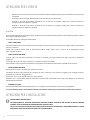
TECHNICAL CHARACTERISTIC TABLES
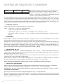
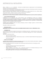
1 Rapid burner 3000 W
2 Semi-rapid burner 1750 W
3 Auxiliary burner 1000 W
5 Double ring burner 3500 W
8 Control knob for burner
Short title or reference to the measurement and calculation methods used to establish compliance with the
above requirements.
The performance of each individual burner is calculated according to standard EN 30-2-1 + A1:2003 + A2:2005
The total e ciency of the hob is calculated according to the EU Regulation 66/2014 Par. 2.2
The e ciency is calculated only for the burners with a nominal capacity exceeding 1,16 KW ( EN 30-2-1 + A1:2003 +
A2:2005; Par. 4.1)
Information which is relevant to the customer to minimize the energy consumption during usage:
Energy Saving Tips: use pots having at base, Use pots with proper size, use pots with lid, minimize the amount of liquid
or fat, when liquid starts boiling reduce the setting.
This product complies with EU Directive 2002/96/EC.
The crossed-out dustbin symbol reported on the appliance indicates that the appliance must be disposed of
separately from other domestic refuse at the end of its useful life. It must therefore be delivered to a waste
recycling centre speci cally for electric and electronic equipment or returned to the retailer at the moment of
purchase of a new equivalent appliance.
The user is responsible for delivering the appliance to the appropriate collection centre at the end of its useful life,
Failure to do so may result in a ne, as provided for by laws governing waste disposal. Di erential collection of waste
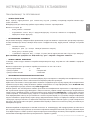
DESCRIPTION
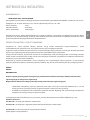
BURNERS
GAS
NORMAL
PRESSURE
mbar
NOMINAL
RATE
INJECTOR
DIAMETER
1/100 mm
TAPE BY
PASS Ø
1/100 mm
NOMINAL
HEAT INPUT
(W) EEgas burner
(%) *
N° DENOMINATION g/h L/h Max.Min.
1 RAPID G30/G31
G20
28-30 / 37
20
218
-
-
286
85
115Y
42
Reg.
3000
3000
950
950 56.7
2 SEMI-RAPID G30/G31
G20
28-30 / 37
20
127
-
-
167
65
97Z
31
Reg.
1750
1750
600
600 57
3 AUXILIARY G30/G31
G20
28-30 / 37
20
73
-
-
95
50
72X
27
Reg.
1000
1000
450
450 /
5 DOUBLE RING G30/G31
G20
28-30 / 37
20
255
-
-
334
93
135
60
Reg.
3500
3500
2100
2100 58.1
TECHNICAL CHARACTERISTIC TABLE
(EEgas hob = 56.9 %) (EEgas hob = 57.4 %)

12 INSTRUCTIONS FOR THE USER
products for eventual recycling, treatment and environmentally friendly disposal helps reduce possible negative e ects
on the environment and health, and also enables the materials making up the product to be recycled. For more detailed
information on the available refuse collection systems, refer to the local Municipal Solid Waste disposal centre or the
shop where the product was purchased. Producers and importers are responsible for ful lling their obligations as regards
recycling, treatment and environmentally friendly disposal by directly or indirectly participating in the collection system.
It is necessary that all the operations regarding the installation, adjustment and adaptation to the type
of gas available are carried out by quali ed personnel, in conformity with the regulations in force.
The speci c instructions are described in the booklet section intended for the installer.
USING THE BURNERS
The symbols silk-screen printed on the side of the knob indicate the correspondence between the knob and the
burner.
• STARTUP WITHOUT VALVES
Turn the corresponding knob anticlockwise up to the maximum position (large ame, g. 1) and press.
• AUTOMATIC STARTUP WITH VALVES
Turn the corresponding knob anticlockwise up to the maximum position (large ame, g. 1) and press the knob. Once
the burner has been started up, keep the knob pressed for about 6 seconds.
• USING THE BURNERS
In order to obtain the maximum yield without waste of gas, it is important that the diameter of the pot is suitable for
the burner potential (see the following table), so as to avoid that the ame goes out of the pot bottom ( g. 2).
Use the maximum capacity to quickly make the liquids reach the boiling temperature, and the reduced capacity to
heat food or maintain boiling. All of the operating positions must be chosen between the maximum and the minimum
ones, never between the minimum position and the closing point.
Use the maximum capacity to quickly make the liquids reach the boiling temperature, and the reduced capacity to
heat food or maintain boiling. All of the operating positions must be chosen between the maximum and the minimum
ones, never between the minimum position and the closing point.
The gas supply can be interrupted by turning the knob clockwise up to the closing position.
If there is no power supply, it is possible to light the burners with matches, setting the knob to the start-up point (large
ame, g. 1).
• NOTICE
• When the equipment is not working, always check that the knobs are in the closing position (see g.1).
• If the ame should blow out accidentally, the safety valve will automatically stop the gas supply, after a few
seconds. To restore operation, set the knob to the lighting point (large ame, g. 1) and press.
• While cooking with fat or oil, pay the utmost attention as these substances can catch re when overheated.
• Do not use sprays near the appliance in operation.
• Do not place unstable or deformed pots on the burner, so as to prevent them from overturning or over owing.
• Make sure that pot handles are placed properly.
• When the burner is started up, check that the ameis regular and, before taking pots away, always lowerthe
ame or put it out.
INSTRUCTIONS FOR THE USER
BURNERS POWER W Ø of pots
Auxiliary 1000 10 - 14 cm
Semi-rapid 1750 16 - 18 cm
Rapid 3000 20 - 22 cm
Double crown 3500 24 - 26 cm

GB
13
INSTRUCTIONS FOR THE USER
CLEANING
Before any operation, disconnect the appliance from the electric grid.
Don’t use a steam cleaner for the cleaning the hob.
It is advisable to clean the appliance when it is cold.
• ENAMELLED PARTS
The enamelled parts must be washed with a sponge and soapy water or with a light detergent.
Do not use abrasive or corrosive products.
Do not leave substances, such as lemon or tomato juice, salt water, vinegar, co ee and milk on the enamelled surfaces
for a long time.
• STAINLESS STEEL PARTS
Stainless steel can be stained if it remains in contact with highly calcareous water or aggressive detergents for an
extended period of time.
The stainless steel parts should also be cleaned with soapy water and then dried with a soft cloth.
• BURNERS AND RACKS
These parts can be removed to make cleaning easier.
The burners must be washed with a sponge and soapy water or with a light detergent, wiped well and placed in their
housing perfectly. Make sure that the ame-dividing ducts are not clogged.
Check that the feeler of the safety valve and the start-up electrode are always perfectly cleaned, so as to ensure an
optimum operation.
• GAS TAPS
The possible lubrication of the taps must be carried out by specialized personnel, exclusively.
In case of hardening or malfunctions in the gas taps, apply to the Customer Service.
INSTRUCTIONS FOR THE INSTALLER
IMPORTANT NOTICE:
THE OPERATIONS INDICATED BELOW MUST BE FOLLOWED BY QUALIFIED PERSONNEL EXCLUSIVELY,
IN CONFORMITY WITH THE REGULATIONS IN FORCE.
THE MANUFACTURING FIRM REFUSES ALL RESPONSIBILITY FOR DAMAGES TO PEOPLE, ANIMALS OR
THINGS, RESULTING FROM THE FAILURE TO COMPLY WITH SUCH PROVISIONS.
INSTALLATION
• INSTALLING THE TOP
The appliance is designed to be embedded into heat-resistant pieces of furniture.
The walls of the pieces of furniture must resist a temperature of 75°C besides the room one.
The equipment must not be installed near in ammable materials, such
as curtains, cloths,etc. Make a hole in the top of the piece of furniture,
with the dimensions indicated in g. 3, at a distance of at least 50 mm
from the appliance border to the adjacent walls.
Any possible wall unit over the cook-top must be placed at a distance of at least 760 mm from the top.
INSTRUCTIONS FOR THE USER
MODEL L (mm) P (mm)
60 560 480

14 INSTRUCTIONS FOR THE INSTALLER
It is advisable to isolate the appliance from the piece of furniture below with a separator, leaving a depression space
of at least 10 mm ( g. 4).
If the hob is going to be installed on the top of an oven, precautions must be taken to guarantee an installation in
accordance with current accident prevention standards. Pay particular attention to the position of the electric cable
and gas pipe: they must not touch any hot parts of the oven.
Moreover, if the hob is going to be installed on the top of a built in oven without forced cooling ventilation, proper
air vents must be installed to guarantee an adequate ventilation, with the lower air entering with a cross section of at
least 200cm2, and the higher air exiting with a cross section of at least 60 cm2.
• FASTENING THE TOP
Every cook-top is equipped with a special washer. A set of hooks is also supplied for mounting the cook-top.
For the installation proceed as follows:
• Remove the racks and burners from the top.
• Turn the appliance upside down and lay the washer S along the external border ( g. 5).
• Introduce and place the cook-top in the hole made in the piece of furniture, then block it with the V screws
of the fastening hooks G ( g.6).
• INSTALLATION ROOM
This appliance is not provided with a device for exhausting the products of combustion.
Regarding room ventilation rules where appliance is installed make reference to the legislation, in conformity with
the local regulations.
• FOR THE U.K. ONLY
The room containing this hotplate should have an air supply in accordance with BS 5440: Part 2: 1989.
• All rooms require an openable window, or equivalent and some rooms will require a permanent vent a well.
• For room volumes up to 5m3 an air vent of 100cm2 is required.
• For room volumes between 5m3 and 10m3 an air vent of 50 cm2 is required.
• If the room is greater than 5m3 and has a door that opens directly to the outside, then no air vent is required.
If there are other fuel burning appliances in the same room BS 5440: Part 2:1989 should be consulted to determine
the air vent requirements.
• GAS CONNECTION
Make sure that the appliance is adjusted for the gas type available (see the label under the appliance). Follow the
instructions indicated in the chapter “gas transformations and adjustments” for the possible adaptation to di erent
gases.
The appliance must be connected to the gas system by means of sti metal pipes or exible steel pipes having
continuous walls, in compliance with the regulations in force.
Some models are equipped with both cylindrical A and conical B connectors for gas supply ( g. 7). Please select the
type which is correct for the supply concerned.
The connection must not stress the gas ramp.
Once the installation is over, check the connection seal with a soapy solution.
• ELECTRIC CONNECTION
The connection to the electric grid must be carried out by quali ed personnel and in conformity with the regulations
in force.
The voltage of the electric system must correspond to the value indicated in the label under the appliance. Make
sure that the electric system is provided with an e ective ground connction in compliance with the regulations and
provisions of the law. Grounding is compulsory.
INSTRUCTIONS FOR THE INSTALLER

GB
15
INSTRUCTIONS FOR THE INSTALLER
GAS TRANSFORMATIONS AND ADJUSTMENTS
• REPLACING THE NOZZLES
If the equipment is adjusted for a type of gas that is di erent from the one available, it is necessary to replace the
burner nozzles.
The choice of the nozzles to replace must be made according to the table of the “technical characteristics” as enclosed.
Act as follows:
• Remove the racks and burners.
• By means of a straight spanner L, unscrew the nozzle U ( g.8) and substitute it with the corresponding one.
• Tighten the nozzle strongly.
• ADJUSTING THE BURNERS
The lowest ame point must always be properly adjusted and the ame must remain on even if there is an abrupt shift
from the maximum to the minimum position.
If this is not so, it is necessary to adjust the lowest ame point as follows:
• start the burner up;
• turn the tap up to the minimum position (small ame);
• remove the knob from the tap rod;
• introduce a at-tip screwdriver in the hole F of the tap ( g.9) and turn the by-pass screw up to a proper
adjustment of the lowest ame point.
As regards G30 gas burners, the by-pass screw must be tightened completely.
MAINTENANCE
• REPLACING THE POWER SUPPLY CABLE
If the power supply cable should be replaced, it is necessary to use a cable with a section of 3x0.75mm2, type H05VV-F
or H05RR-F, complying with the regulations in force.
The connection to the terminal board must be e ected as shown in g. 10 - 10/A:
brown cable L (phase)
blue cable N (neutral)
green-yellow cable (ground)
The manufacturing rm refuses all responsibility for any possible imprecision in this booklet, due to misprints or clerical
errors. It reserves the right to make all the changes that it will consider necessary in its own products, without e ecting
the essential characteristics of functionality and safety.
INSTRUCTIONS FOR THE INSTALLER

16

RU
17
1717
,
. , , -
- .
,
.
. 3-
, , .
:
, ,
, , .
• , -
.
• .
• .
• .
• ,
.
• , -
(. «»).
• - , -
, .
• . -
.
• .
, , (. «»).
•
(. «»).
•
, .
:
.
•
, , ,
.
-
. 0-800-500-514,
www.freggia.com
Freggia. , -
- ( 0-800-500-514 -
), , .
, . -
- , -
, .
, ,
, .
,
, .
ОБЩИЕ РЕКОМЕНДАЦИИ ПО ИСПОЛЬЗОВАНИЮ

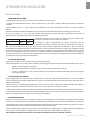
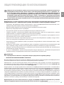
1 3000 5 3500
2 1750 8
3 1000
, -
EN 30-2-1 + A1:
2003 + A2: 2005.
66/2014 . 2.2.
1,16 (EN 30-2-1 + A1:
2003 + A2: 2005; . 4.1).
,
.
, , .
. -
.
EU 2002/96/EEC.
« » ,
. -
-
.
18
ТАБЛИЦА ТЕХНИЧЕСКИХ ХАРАКТЕРИСТИК
ОПИСАНИЕ РАБОЧЕЙ ПОВЕРХНОСТИ
1/100
1/100
()
EEgas burner
(%) *
N° / /
..
1 G30/G31
G20
28-30 / 37
20
218
-
-
286
85
115Y
42
Reg.
3000
3000
950
950 56.7
2 G30/G31
G20
28-30 / 37
20
127
-
-
167
65
97Z
31
Reg.
1750
1750
600
600 57
3
G30/G31
G20
28-30 / 37
20
73
-
-
95
50
72X
27
Reg.
1000
1000
450
450 /
5A
A
G30/G31
G20
28-30 / 37
20
255
-
-
334
93
135
60
Reg.
3500
3500
2100
2100 58.1
(EEgas hob = 56.9 %) (EEgas hob = 57.4 %)

RU
19
19
, -
. , -
. , ,
,
, .
-
, .
,
. -
, .
, , .
•
«» ( .1)
.
•
«» ( .1)
.
, 6 .
•
,
(. ). -
- (. 2).
,
.
«» «». «-
» «».
, «».
, -
( . 1).
• !
• , «» (. 1), -
.
• , - . -
( . 1) .
• ,
.
• .
ИНСТРУКЦИИ ДЛЯ ПОЛЬЗОВАТЕЛЯ
() Ø
1000 10 - 14
1750 16 - 18
3000 20 - 22
a a 3500 24 - 26

20
• , -
.
• , , .
• , .
.
, -
. .
, .
•
.
. , ,
, , , .
•
, -
. -
. ,
.
•
, .
, . -
. , .
(-) . -
.
•
, , -
.
, .
ИНСТРУКЦИИ ДЛЯ УСТАНОВЩИКА
:
-
.
, -
, .
•
, .
75° -
.
ИНСТРУКЦИИ ДЛЯ ПОЛЬЗОВАТЕЛЯ
Strona się ładuje...
Strona się ładuje...
Strona się ładuje...
Strona się ładuje...
Strona się ładuje...
Strona się ładuje...
Strona się ładuje...
Strona się ładuje...
Strona się ładuje...
Strona się ładuje...
Strona się ładuje...
Strona się ładuje...
Strona się ładuje...
Strona się ładuje...
Strona się ładuje...
Strona się ładuje...
Strona się ładuje...
Strona się ładuje...
Strona się ładuje...
Strona się ładuje...
-
 1
1
-
 2
2
-
 3
3
-
 4
4
-
 5
5
-
 6
6
-
 7
7
-
 8
8
-
 9
9
-
 10
10
-
 11
11
-
 12
12
-
 13
13
-
 14
14
-
 15
15
-
 16
16
-
 17
17
-
 18
18
-
 19
19
-
 20
20
-
 21
21
-
 22
22
-
 23
23
-
 24
24
-
 25
25
-
 26
26
-
 27
27
-
 28
28
-
 29
29
-
 30
30
-
 31
31
-
 32
32
-
 33
33
-
 34
34
-
 35
35
-
 36
36
-
 37
37
-
 38
38
-
 39
39
-
 40
40


Freggia HF640GX Instrukcja obsługi
- Kategoria
- Płyty
- Typ
- Instrukcja obsługi
w innych językach
- italiano: Freggia HF640GX Manuale utente
- English: Freggia HF640GX User manual
- русский: Freggia HF640GX Руководство пользователя
Powiązane artykuły
Inne dokumenty
-
Foster 7039632 Instrukcja obsługi
-
Candy PL 40 AW GH Instrukcja obsługi
-
HOTPOINT/ARISTON TQ640(DS) K GH/HA EE instrukcja
-
HOTPOINT/ARISTON TQG 641 /HA (CF) instrukcja
-
-
Indesit PL 640S (IX)/HA (PL) instrukcja
-
-