Triton TWX7 Instrukcja obsługi

Kategoria
Elektronarzędzia
Typ
Instrukcja obsługi
TWX7 RT001
Router Table Module
tritontools.com
Version date: 17.08.2016
Assembly Instructions
Montage instructies
Instruções de montagem
Instructions de montage
Instrukcja montażu
Aufbauanleitung
Инструкции по сборке
Istruzione assemblaggio
Összeszerelési utasítások
Instrucciones de montaje
Pokyny k sestavení
Pokyny na zostavenie
Montaj Talimatları
2
15
272625
24
23
22
21
1
20 19
18
17 16
14
13
12
1098765432 11
3
P1-1 ×1
P1-2 ×7
P1-3 ×2
P1-4 ×2
P1-5 ×3
P1-6 ×1
P1-7 ×1
P2-1 ×1
P2-2 ×2
P2-3 ×4
P2-4 ×4
P2-5 ×4
P2-6 ×4
P2-7 ×4
A
P1-12
P1-13
P1-14
III TRA001
II MOF001
IJOF001
P1-2
P1-11
P1-8
P1-9
P1-7
P1-10
P1-2
P1-1
P1-2
P1-4
P1-3
P1-4
P1-3
P1-5
P1-5
P1-5
P1-2
P1-2
P1-6
P2-15 ×2
P2-16 ×2
P2-17 ×2
P2-18 ×2
P3-1 ×1
P3-2 ×1
P3-3 ×1
P4-2 ×2
P4-3 ×12
P4-4 ×2
P4-5 ×4
P4-6 ×12
P1-8 ×1
P1-9 ×1
P1-10 ×3
P1-11 ×3
P1-12 ×1
P1-13 ×1
P1-14 ×1
P2-8 ×2
P2-9 ×2
P2-10 ×2
P2-11 ×2
P2-12 ×2
P2-13 ×2
P2-14 ×2
P3-4 ×2
P3-5 ×4
P3-6 ×4
P3-7 ×2
P3-E ×1
P3-U ×1
P4-1 ×4
4
B
C
P2-6
P2-2
P2-4
P2-5
P2-7
P2-3
P3-6
P2-1
P2-8
P3-3
P3-5
P3-E / P3-U
P3-2
P3-7
P3-6
P3-5
P3-1
5
D
P3-4 P3-4
F
E
P2-14
P2-12
P2-11
P2-10
P2-16
P2-18
P2-17
P2-9
P2-15
P2-13
6
G
P4-3
P4-5
P4-1
P4-6
H
7
I
J
P4-3
P4-1
P4-6
P4-4
P4-2
K
8
M
N
L
3
4
5
6
7
8
9
11
1
0
1
2
1
2
2
1
3
4
9
Q
O
P
10mm Min
10mm Min
P3-4
P3-4
10
R
11
GB
T
S
1
Version date: 23.11.2016
TWX7 RT001
Router Table Module
tritontools.com
Operating and Safety Instructions
Bedienings- en
veiligheidsvoorschriften
Instruções de
Operação e Segurança
Instructions d’utilisation
et consignes de sécurité
Instrukcja obsługi
i bezpieczestwa
Gebrauchs- und
Sicherheitsanweisung
Инструкции по эксплуатации и
правила техники безопасности
Istruzioni per l’uso
e la sicurezza
Kezelési és
biztonsági utasítások
Instrucciones de
uso y de seguridad
Provozní a
bezpečnostní pokyny
Prevádzkové a bez-
pečnostné pokyny
Çalıma ve
Güvenlik Talimatları
2
GB
Original Instructions
Part no: TWX7RT001
Compatible routers:
Triton TRA001
Triton MOF001
Triton JOF001
Router module size: 660 x 410mm
Workcentre table size: 904 x 708mm
Extruded fence size: 680 x 85mm
Extruded fence thickness: 21.4mm
MDF fence face size (x 2): 340 x 75mm
Max MDF fence face opening: 90mm
Fence adjustable position: +25/-125mm
Fence micro adjusters: 1mm (one full revolution)
Spacer bar settings: 0.5, 1.0, 1.5, 2.0mm
Guard height: 0-76mm
Featherboard stack height: 1: 9.5mm, 2: 15mm, 3: 44mm, 4: 50mm
Maximum throat plate router
bit diameter (Dmax);
Large - 50mm
Medium - 40mm
Small - 20mm
Dust Extraction fitting (Dia): 31.75mm High Pressure / 62.5mm Low Pressure
Net weight: 9.9kg
Specication
Description of Symbols
Wear hearing protection
Wear eye protection
Wear breathing protection
Wear head protection
Wear hand protection
Read instruction manual
Be aware of kickback!
Warning: Sharp blades or teeth!
Indoors use only!
DO NOT use in rain or damp environments!
WARNING: Moving parts can cause crush and cut injuries.
Caution!
Toxic fumes or gases!
DO NOT touch! DO NOT access the guard without removing the power. Keep children and bystanders away while operating a
power tool. Distractions can cause you to lose control. All visitors should be kept safe distance from work area.
Always disconnect from the power supply when adjusting, changing accessories, cleaning, carrying out maintenance and when
not in use! s can cause you to lose control. All visitors should be kept safe distance from work area.
General Safety
WARNING! When using electric power tools, basic safety precautions should always be followed to reduce the risk of fire, electric shock and
personal injury including the following safety information. Read all these instructions before attempting to operate this product and save these
instructions for future use.
WARNING: This appliance is not intended for use by persons (including children) with reduced, physical or mental capabilities or lack of
experience or knowledge unless they have been given supervision or instruction concerning use of the appliance by a person responsible for
their safety. Children must be supervised to ensure that they do not play with the appliance.
CAUTION: Use the power tool, accessories and tool bits etc. in accordance with these instructions, taking into account the working conditions
and the work to be performed. Use of the power tool for operations different from those intended could result in a hazardous situation.
The term “power tool” in the warnings refers to your mains-operated (corded) power tool or battery-operated (cordless) power tool.
1 - Keep work area clear - Cluttered areas and benches invite injuries
2 - Consider work area environment
- Do not expose tools to rain
- Do not use tools in damp or wet locations
- Keep work area well lit
- Do not use tools in the presence of flammable liquids or gases
3 - Guard against electric shock - Avoid body contact with earthed or grounded surfaces (e.g. pipes, radiators, ranges, refrigerators)
4 - Keep other persons away - Do not let persons, especially children, not involved in the work touch the tool or the extension cord and keep
them away from the work area
5 - Store idle tools - When not in use, tools should be stored in a dry locked-up place, out of reach of children
6 - Do not force the tool - It will perform the job better and safer at the rate for which it was intended
7 - Use the right tool - Do not force small tools to do the job of a heavy duty tool.
Do not use tools for purposes not intended; for example, do not use circular saws to cut tree limbs or logs
8 - Dress appropriately
- Do not wear loose clothing or jewellery, which can be caught in moving parts
- Suitable safety footwear is recommended when working outdoors
- Wear protective covering to contain long hair
9 - Use protective equipment
- Use safety glasses
- Use face or dust mask if working operations create dust
WARNING: Not using protective equipment or appropriate clothing can cause personal injury or increase the severity of an injury.
10 - Connect dust extraction equipment - If the tool is provided for the connection of dust extraction and collecting equipment, ensure these
are connected and properly used
11 - Do not abuse the power cable - Never yank the power cable to disconnect it from the socket. Keep the power cable away from heat, oil
and sharp edges. Damaged or entangled power cables increase the risk of electric shock
12 - Secure work - Where possible use clamps or a vice to hold the work. It is safer than using your hand
13 - Do not overreach - Keep proper footing and balance at all times
14 - Maintain tools with care
- Keep cutting tools sharp and clean makes the tool easier to control and less likely to bind or lock in the workpiece
- Follow instruction for lubricating and changing accessories
- Inspect tool power cables periodically and if damaged have them repaired by an authorized service facility
- Inspect extension cables periodically and replace if damaged
- Keep handles dry, clean and free from oil and grease
WARNING: Many accidents are caused by poorly maintained power tools.
15 - Disconnect tools - When not in use, before servicing and when changing accessories such as blades, bits and cutters, disconnect tools
from the power supply
WARNING: The use of accessories or attachments not recommended by the manufacturer may result in a risk of injury to persons.
16 - Remove adjusting keys and wrenches - Form the habit of checking to see that keys and adjusting wrenches are removed from the tool
before switching it on
17 - Avoid unintentional starting - Ensure switch is in “off’ position when connecting to a mains socket or inserting a battery pack, or when
picking up or carrying the tool
WARNING: Unintended starting of a tool can cause major injuries.
18 - Use outdoor extension leads - When the tool is used outdoors, use only extension cords intended for outdoor use and so marked. Use of
an extension cable suitable for outdoor use reduces the risk of electric shock
19 - Stay alert
Technical Abbreviations Key
VVolts
~, AC Alternating current
A, mA Ampere, milli-Amp
n0No load speed
ØDiameter
°Degrees
λWavelength
Hz Hertz
, DC Direct current
W, kW Watt, kilowatt
/min or min-1 Operations per minute
dB(A) Decibel sound level (A weighted)
m/s2Metres per second squared (vibration magnitude)
Thank you for purchasing this Triton tool. This manual contains information necessary for safe and effective operation of this
product. This product has unique features and,
even if you are familiar with similar products, it is necessary to read this manual carefully to ensure you fully understand the
instructions. Ensure all users of the tool read and fully understand this manual.
Introduction
The rating plate on your tool may show symbols. These represent important information about the product or instructions on its use.
3
GB
- Watch what you are doing, use common sense and do not operate the tool when you are tired
- Do not use a power tool while you are under the influence of drugs, alcohol or medication
WARNING: A moment of inattention while operating power tools may result in serious personal injury.
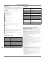
20 - Check damaged parts
- Before further use of tool, it should be carefully checked to determine that it will operate properly and perform its intended function
- Check for alignment of moving parts, binding of moving parts, breakage of parts, mounting and any other conditions that may affect its
operation
- A guard or other part that is damaged should be properly repaired or replaced by an authorized service centre unless otherwise
indicated in this instruction manual
- Have defective switches replaced by an authorized service centre
WARNING: Do not use the tool if the on/off switch does not turn it on and off. The switch must be repaired before the tool is used.
21 - Have your tool repaired by a qualified person - This electric tool complies with the relevant safety rules. Repairs should only be carried
out by qualified persons, otherwise this may result in considerable danger to the user
WARNING: When servicing use only identical replacement parts.
WARNING: If the power cable is damaged it must be replaced by the manufacturer or an authorised service centre.
22 - Power tool mains plugs must match the mains socket - Never modify the plug in any way. Do not use any adapter plugs with earthed
(grounded) power tools. Unmodified plugs and matching sockets will reduce risk of electric shock
23 - If operating a power tool outside use a residual current device (RCD) - Use of an RCD reduces the risk of electric shock
NOTE: The term “residual current device (RCD)” may be replaced by the term “ground fault circuit interrupter (GFCI)” or “earth leakage circuit
breaker (ELCB)”.
WARNING: When used in Australia or New Zealand, it is recommended that this tool is ALWAYS supplied via Residual Current Device (RCD)
with a rated residual current of 30mA or less.
Router Table Safety
WARNING: ALWAYS wear personal protective equipment;
Hearing protection to reduce the risk of induced hearing loss
Respiratory protection to reduce the risk of inhalation of harmful dust
Cut-proof no-fray gloves to avoid possible injuries when handling router cutters and rough material due to sharp edges.
Any gloves where fabric material can work loose with the possibility of fabric strands MUST not be used when operating the
router table
Safety glasses to avoid eye injury caused by flying particles
Ensure all people in the vicinity of the work area use adequate protection. Keep bystanders a safe distance away.
WARNING: ALWAYS connect the dust extraction port on the router cutter guard to a suitable vacuum dust extraction system.
Certain types of wood are toxic or may cause allergic reactions in people and animals, especially when exposed to very fine dust. ALWAYS
wear appropriate respiratory protection in addition to vacuum dust extraction.
a) ONLY fit plunge routers that are listed as compatible in ‘Specification’ to the Router Table. Only fit router bits that are
suitable for the installed plunge router, with shanks compatible with the collet installed.
b) NEVER reach to the underside of the router table when the router is connected to the power supply.
c) ALWAYS remove the router plunge spring and plastic base plate, before fitting the tool to the router table.
This enables easy router bit change and height winder adjustment from above the table.
d) Keep your hands away from the cutting area. NEVER pass your hands directly over, or in front of, the revolving cutter.
As one hand approaches the router bit, move it AWAY from the cutter, in an arc motion over the top of the router bit, to the
out-feed side beyond the cutter. NEVER trail your fingers behind the workpiece and DO NOT use awkward hand positions.
Use push sticks and blocks where necessary.
e) Do not attempt to perform tasks on workpieces shorter than 300mm (12") in length without using special fixtures or
jigs. It is recommended to make work pieces oversize then cut to finished length.
f) ASSESS risks, benefits and alternatives BEFORE using push sticks, push blocks or other jigs and safety devices.
In many applications the use of such contraptions is useful and safe, however, in others it can be dangerous. Push sticks can
fly out of the operator’s hand, when they come into contact with the revolving router bit, potentially causing serious injuries.
g) ALWAYS support large workpieces on the in-feed and out-feed sides of the router table, and where necessary, also to
the sides. Use Triton Sliding Extension or Multi-stand wherever possible.
h) ALWAYS use guards, fences, horizontal and vertical featherboards etc., to guide the workpiece, counteract and avoid
kickback, especially when routing small or narrow workpieces. Vertical featherboards attached to the fence also help
prevent uncontrolled lift-up of the workpiece.
i) ALWAYS remove ALL loose objects from the table before operating. Vibrations may cause loose objects to move, and
come into contact with the cutter.
j) NEVER attempt to remove wood fragments or dust from the cutter with your hands, whilst the router bit is spinning.
ALWAYS switch the router off, disconnect the machine from the power supply, and wait until the cutter has come to a
standstill. ALWAYS use cut-proof gloves when touching the cutter, to avoid injury.
k) ALWAYS inspect the workpiece for nails, staples and other metal objects and foreign bodies. If the router cutter hits a
concealed nail, the bit may be destroyed, high-velocity projectiles may be produced, kickback can occur, all of which can lead
to serious injury.
l) WHEREVER possible, use blind cutting techniques, where the router bit does not protrude from underneath the
workpiece. Keeping the cutter on the underside of the workpiece provides additional operator protection.
m) ONLY expose the smallest possible part of the cutter above the table surface. Keep any unused portion of the cutter
below the table surface.
n) ALWAYS test any new setup by rotating the spindle by hand, with the machine disconnected from the
power supply. Ensure proper cutter clearance to the throat place, fence and guard, before starting the machine.
o) ALWAYS use suitable throat plates, providing optimum clearance around the router bit.
p) ALWAYS use the router cutter guard, and adjust the guard to cover as much of the router bit as possible, as close to the
workpiece as possible. This not only protects the user from accessing the revolving router cutter, it also provides effective
dust extraction
q) LIMIT the depth of cut; NEVER remove too much material in one pass. Several passes with at smaller cutting depth are
safer, and produce a better surface finish.
r) ENSURE to adjust the router cutter speed, according to router cutter diameter and material being cut. Use the speed
selection dial on the plunge router.
s) ALWAYS feed AGAINST the rotation of the cutter. Both feed direction and rotation are indicated by arrows on the
router table surface.
t) ALWAYS use the fence if using a cutter without bearing or pilot. ALWAYS support the workpiece firmly against the fence.
NEVER remove the retractable guards on the fence. ALWAYS use a cutter with bearing or pilot for freehand work.
Additional Safety Information
ONLY use router cutters in perfect working condition compatible with the specification of the router table and which are
suitable for hand feeding operation (marked ‘MAN’ for manual operation according to EN 847-1)
The bit must not enter the workpiece in the same direction as the feed direction. If this occurs, it is likely to cause climb
cutting, causing the workpiece to climb and pull away from the operator. This can lead to a loss of control and a potential
hazard during operation
Do not attempt to re-sharpen router cutters unless you specifically follow the manufacturer’s instructions and have the
equipment to complete this task. The majority of router cutters have blades that cannot be re-sharpened and must be
replaced immediately if dull
Do not create fence traps caused by improper fence location. Fence traps happen when the fence is positioned so far back that the front
side of the workpiece would be behind the router cutter. These are dangerous due to the risk of climb cutting and the difficulty of keeping
the workpiece against the fence
Ensure the correct table insert (table ring) is fitted that is the correct size for the size of the router cutter fitted
Never use a router table until fully assembled and always re-check fasteners after re-assembly after storage
Make certain the router is not plugged into the power outlet when installing into the table or when making
adjustments or changing accessories
DO NOT plug the router into a standard mains wall socket. It must be plugged into the router table switch box so it can be
switched off in an emergency
The router table must be installed on a solid level surface and secured so the table will not tip. Use of auxiliary in-feed and out-feed
supports is necessary for long or wide workpieces. Long workpieces without adequate support could cause the table to tip towards the
operator causing injury
Routers create a lot of vibration and can work loose from their mountings. Check the mountings frequently and re-tighten if
necessary
Never start the tool with the router cutter already engaged in the workpiece. This can lead to a lack of control and possible injury
The router table is designed to cut flat, straight and squared material only. Do not cut material that is warped, uneven, weak or made from
inconsistent material. If necessary make sure material is correctly prepared before use. Incorrect material can lead to a lack of control
and possible injury
WARNING: Unmaintained tools can cause uncontrolled situations. ONLY use router cutters that are correctly sharpened, maintained
and adjusted in accordance with the manufacturer’s instructions.
Note: Seek professional training and assistance before attempting work that require procedures you are not familiar with. STOP using the
router table, if, at any point during operation, you encounter difficulties or are uncertain how to proceed safely.
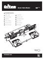
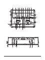
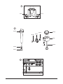
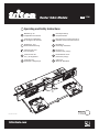
Product Familiarisation
1. Horizontal Featherboard T-Slot
2. Fence Face Spacer
3. Module Levelling Screw
4. Fence Micro-Adjuster
5. Vertical Featherboard
6. Guard Knob
7. Extraction Connector
8. Fence
9. Fence Knob
10. Table Scale
11. Module Levelling Screw
12. Thumb Hole
13. Featherboard Adjuster Knob
14. Fence Face
15. Module Mounting Rollers & Tracks
16. Cutter Height Winder Slot
17. Guard
18. Direction Indicator
19. Horizontal Featherboard
20. Featherboard T-Slot Knob
21. Featherboard Adjuster Knob
22. Module Levelling Bobbin Screw
23. Fence Face Adjustment Knob
24. Micro-Adjuster
25. Fence Slot
26. Fence Micro-Adjuster Knob
27. Table Scale Indicator
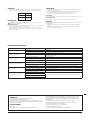
Intended Use
An effective router table capable of edge rebating, trenching, cross trenching, planing, edge moulding (fence and free hand), end grain work,
using a template guide, and morticing. For use with the Triton Workcentre TWX7 and Triton Routers.
Unpacking Your Tool
Carefully unpack and inspect your new tool. Familiarise yourself with all its features and functions
Ensure that all parts of the tool are present and in good condition. If any parts are missing or damaged, have such parts
replaced before attempting to use this tool
IMPORTANT: Read these instructions in combination with the instructions supplied with your Triton router and the Triton Workcentre.
For instruction video, please go to www.tritontools.com
Before Use
WARNING: Ensure the router is switched off and disconnected from the power supply before attaching or changing any accessories,
inserting or removing modules or making any adjustments.
Installing and removing the router module
See ‘Installing and removing modules’ in the main Workcentre TWX7 manual for a complete guide.
WARNING: Lower the router cutter to a safe height position before installing or removing the router table module.
WARNING: Some modules are heavy, especially with power tools installed. ALWAYS grip modules with both hands, ensure secure footing,
stand upright, and avoid awkward movements when removing and fitting modules
IMPORTANT: Always lower modules carefully using both the provided Thumb Holes. Uncontrolled lowering can cause Workcentre, module and
power tool damage as well as possible injury to the operator.
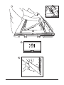
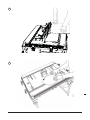
WARNING: Do not place fingers and/or body parts between the module and the Workcentre chassis. See Fig. L
To remove: Toggle the Module Locks to the unlocked position (see Fig. M). Using both Thumb Holes (12) to tilt the module to 45° then slide
and lift out
To insert: Locate the Module Mounting Rollers in the Module Mounting Tracks (15) as a hinging point and lower the insert down. Use the
Thumb Holes to lower to a level position and then re-lock the Module Locks
Note: Modules can be stood upright by angling them to around 120°. This position can be used when adjustments on the underside of
modules are necessary, e.g. adjustments to the fitted power tools, and there is no need to remove the module.
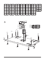
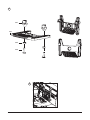
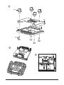
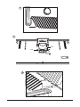
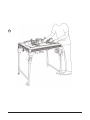
Assembling the router table module
Use the Figures provided; A-K to assemble the router table module. Step B requires additional information below.
Note: P1-6 on Fig.A is the Starting Pin for freehand operation and only requires fitting for freehand operation.
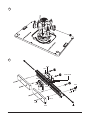
Fitting a Triton router to the router mounting plate
The mounting plate is on the underside of the table and has been designed for direct mounting of any of the three
Triton Routers (JOF001, MOF001 and TRA001)
WARNING: Remove the plunge spring to configure the router for table-mounted operation. See the original router manual for procedure. Store
the spring carefully as it will need to be re-fitted when the router is removed from the router table module.
1. Remove the plastic cover of the base plate of the router by removing the securing screws. The screws and plastic base plate
should be safely stored for when they may need to be re-fitted in the future
2. Ensure the base of the router is completely clean so it will be level with the mounting plate when fitted
3. Loosen the two mounting knobs on the router until they are approximately 10mm above the base of the router when
pushed down
4. Push down on the mounting knobs until the bolt heads locate into the keyholes and rotate the router anticlockwise until the knobs align
with the small triangle holes (Fig. B)
5. Tighten the mounting knobs firmly
6. Ensuring all mains power is switched off, connect the power cable plug of the power tool to the mains socket of the
Workcentre not directly to a wall socket or other mains outlet
Note: Early Triton TRA001 routers do not feature a table winder connector.
Levelling the throat plate
1. Level the throat plate in the router table using a square and the supplied hex key to adjust the levelling screws (see Fig. N)
2. Fit the three Throat Plate Screws (P8) to secure the throat plate in position
3. Check the throat plate is level with the table surface
IMPORTANT: Always ensure the correct throat plate is used for the fitted router bit.
Levelling the router module
All modules must be adjusted so they are level with the Workcentre chassis, to achieve accurate results and for safe
operation. Therefore all modules are equipped with seven Module Levelling Screws (11)
1. Fit the module into the Workcentre chassis and lock both Module Locks (20)
2. Tighten the three Module Levelling Bobbin Screws (11), until there is no movement between the module and the Workcentre
4
GB
chassis
3. Place a straight edge over the corner, across the levelling screws, and check for gaps
4. Adjust the Module Levelling Screws, using the provided hex key, until both sides of the corner are flush with the Workcentre
chassis
5. Repeat for the remaining three corners and the single Module Levelling Screw in the middle of the long side of the module.
6. Check all sides of the module are flush with the Workcentre chassis by placing a straight edge over the module,
perpendicular to the long and short sides, as well as diagonally over the table. Fine-adjust and re-check where necessary
Dust extraction
WARNING: ALWAYS use a suitable vacuum cleaner or workshop dust extraction system.
WARNING: Some dust from natural wood , surface coatings and composite materials contains toxic substances. ALWAYS dispose of harmful
dust according to laws and regulations.
While dust extraction can be achieved using any vacuum cleaner, domestic (bag-type) units can fill up very quickly. For a much larger
capacity, consider fitting a Triton Dust Collector (DCA300) to your vacuum cleaner
The combined electrical load of the router and vacuum cleaner may exceed the rated amperage of the domestic extension lead or power
outlet. Always connect the vacuum cleaner and router to separate electrical outlets, and switch on both
appliances separately
Operation
WARNING: ALWAYS wear eye protection, adequate respiratory and hearing protection, as well as suitable gloves, when working with
this tool.
IMPORTANT: The router table is marked with the feed direction. This indicates the correct and safest direction for the workpiece when making
the cut.
WARNING: Do not over-balance the Workcentre by using very large workpieces.
Note: Refer to your original TWX7 Workcentre instructions for full information and diagrams that refer to parts of the Workcentre.
Workcentre switchbox operation
IMPORTANT: The switchbox requires a live mains connection to switch ON. It will reset to OFF as soon as power is disconnected and require
resetting to ON when power is restored to continue operation.
Switching on and off
Note: Refer to your router manual for additional information
1. The Workcentre ON/OFF Switch is located at the front
2. Connect the Workcentre mains lead to a wall socket and switch on
3. Switch the Workcentre ON/OFF Switch into the ‘O’ position by pushing on the emergency stop flap
4. Switch on the power tool by pressing the ON/OFF Switch into the ‘I’ position
5. Switch the Workcentre ON/OFF Switch into the ‘I’ position to power the tool to use
Press down on the emergency stop flap to switch off
User position and feed direction
The main user position is defined by the location of the safety cut-off switch
ALWAYS remain positioned in close proximity to the switch, so the machine can be instantly switched off in the case of
emergency
Feed workpieces from this position in the direction indicated by the arrows on the table surface of the individual module
Fitting and removing router bits
WARNING: Do not use Router Cutters that exceed 50mm in diameter with the router table module.
1. Switch off the router with the power switch fitted to the tool itself
2. Fit the table winder through the router table and wind to raise the router cutter and collet
3. Use the router collet spanner to remove and replace the existing router bit
4. Wind the table winder so the router bit is at the correct height position
5. Ensuring the Workcentre power switch is set to ‘Off’, return the router on/off switch to the on/position
IMPORTANT: Do not use the table winder while the router is powered.
IMPORTANT: Refer to the router manual for details of compatible router bit types and sizes.
Using the guard
Ensure the Guard (17) is used whenever possible and set to the correct height position to ensure maximum
protection for the operator’s hands
Using the fence micro adjusters
1. Screw the thumbwheels on the Fence Micro-Adjusters (4) out to provide sufficient adjustment. Tighten the micro-adjusters in
position against the rear of the fence and screw the thumbwheels in to obtain the required rebate amount. One complete turn is 1mm
2. Unlock the fence, move it back against the micro-adjusters and re-lock
Using the fence
The Fence Faces (14) should always be positioned as close to the cutter as possible. Position them by sliding forward or
backward. Ensure they are tensioned firmly enough to resist unwanted movement
Using the featherboards
IMPORTANT: Horizontal and vertical featherboards should not overlap in use. A minimum gap of 10mm is required. See Fig. Q
Both the Vertical Featherboard (5) and Horizontal Featherboard (19) are used to apply light pressure to the workpiece to hold it more securely
as it is cut.
Each featherboard has a short plastic pin (Fig O): this indicates the workpiece line. Adjust both the Vertical Featherboard and
Horizontal Featherboard so this shorter pin just touches the workpiece so the longer pins are correctly tensioned against the
workpiece in use
The exposed router bit cutter height should not exceed the height of the installed horizontal featherboards. Horizontal
featherboards can be stacked to allow for a higher exposed cutter and taller workpieces. This is an additional purchase
TWX7FB.
Stacked 1 2 3 4
Height 9.5mm 15mm 44mm 50mm
Using the fence spacers
Planing cuts should be performed with the cutter mostly hidden behind the Fence Faces (14) (Fig. R & S)
WARNING: NEVER make planing cuts with the workpiece passing between the cutter and fence on the right. The cutter will flex aside, ‘climb
up’ on the work, and rip the workpiece out of your hands - or even pull your hand into the cutter
Planing on the router fence
Planing cuts of 0.5, 1.0, 1.5 and 2.0mm can be performed using the Fence Face Spacers (2)
Method 1
1. Ensure the Fence Faces are close to the cutter
2. Push the spring-loaded left Fence Face away from the fence and slide the two Fence Face Spacers into the gaps
created at the required rotation for the maximum cut depth required as marked on the spacer
3. Use a wooden straight edge to align the cutter blade with the left Fence Face only. Begin the cut
Method 2
1. Ensure the Fence Faces are close to the cutter
2. Set Micro-Adjusters (24) to mid travel; ensure marks are aligned
3. Use a wooden straight edge to align the cutter blade with the Fence Faces. Push the Micro-Adjusters into contact with the
Fence. Lock the Fence in this position
4. Decide on cut depth required. Wind both Micro-Adjusters clockwise by this depth. Unlock the Fence and push back into
contact with the Micro-Adjusters
5. Push the spring-loaded left Fence Face away from the Fence and slide the two Fence Face Spacers into the gaps created at the required
rotation for the maximum cut depth required as marked on the spacer. Begin the cut
Fitting the starting pin
A Starter Pin can be fitted to the router table to assist freehand routing. For freehand operation, configure the router table as Fig. P
Ensure the guard is correctly adjusted to the correct height to provide maximum protection to the operator’s hands (Fig. T)
In use, the workpiece should contact the starter pin first and be angled from that position to the cutter for the first cut
Accessories
A wide range of accessories and consumables, in addition to those listed below, is available from your Triton stockist.
Spare parts can be obtained from toolsparesonline.com
Triton code Description
TWX7P Protractor
TWX7FB Featherboard Pack
Maintenance
WARNING: ALWAYS disconnect from the power supply before carrying out any inspection, maintenance or cleaning.
General inspection
Check regularly that all the fixing screws are tight and all parts are undamaged and in good condition. Do not use the router table until
any faulty, damaged or heavily worn parts are replaced
Inspect the supply cord of the tool, prior to each use, for damage or wear. Repairs should be carried out by an authorised Triton service
centre. This advice also applies to extension cords used with this tool
Cleaning
Keep your tool clean at all times. Dirt and dust will cause internal parts to wear quickly, and shorten the machine’s service life. Clean the
body of your machine with a soft brush, or dry cloth. If available, use clean, dry, compressed air to blow through
the ventilation holes
Clean the tool casing with a soft damp cloth using a mild detergent. Do not use alcohol, petrol or strong cleaning agents
Never use caustic agents to clean plastic parts
Lubrication
Slightly lubricate all moving parts at regular intervals with a suitable spray lubricant
Storage
Store this tool carefully in a secure, dry place out of the reach of children
Disposal
Always adhere to national regulations when disposing of power tools that are no longer functional and are not viable for repair.
Do not dispose of power tools, or other waste electrical and electronic equipment (WEEE), with household waste
Contact your local waste disposal authority for information on the correct way to dispose of power tools
5
GB
Troubleshooting
Problem Possible cause Solution
No function when power turned on
No power Check power supply
Router unit’s power switch is off Reset router power switch
Table module is not level
Levelling screws are not correctly adjusted Refer to ‘Levelling the router module’ section
Rough surface Ensure the Workcentre is situated on a secure flat surface. Relocate the table if the ground is found to be rough
Unknown mechanical noise
Check router cutter is correctly fitted Tighten collet assembly
Other fittings have worked loose Check fittings
Router has worked loose from router mounting Secure router correctly and tighten fittings
Large amount of chippings and dust in use
Check vacuum system bag or cylinder is not full Replace bag or empty cylinder
Check dust extraction is switched on Switch on
Check dust extraction is properly connected Make sure everything is correctly assembled along the whole dust extraction assembly and hose
Poor quality results
Check router cutter is sharp and in good condition Replace if dull or worn
Check router speed is correct Set the speed correctly on router unit
Cut is too deep per pass Complete work in multiple passes
Workpiece difficult to control
Workpiece incorrectly positioned
Read Router Table Safety section and also refer to your original Router Manual for additional safety information
Fence incorrectly positioned
Workpiece direction incorrect
Featherboards not correctly used
Guarantee
To register your guarantee visit our web site at
www.tritontools.com* and enter your details.
Your details will be included on our mailing list (unless indicated otherwise)
for information on future releases. Details provided will not be made available to any third party.
Purchase Record
Date of Purchase: ___ / ___ / ____
Model: TWX7RT001 Retain your receipt as proof of purchase art pr
Triton Precision Power Tools guarantees to the purchaser of this product that if any part proves to be defective due to faulty
materials or workmanship within 3 YEARS from the date of original purchase, Triton will repair, or at its discretion replace, the
faulty part free of charge.
This guarantee does not apply to commercial use nor does it extend to normal wear and tear or damage as a result of accident,
abuse or misuse.
* Register online within 30 days.
Terms & conditions apply.
This does not affect your statutory rights oves to be defecti
GB
6
NL
Modelnummer: TWX7RT001
Compatibele bovenfrezen:
Triton TRA001
Triton MOF001
Triton JOF001
Freestafelblad afmetingen: 660 x 410 mm
Workcenter tafelblad afmetingen: 904 x 708 mm
Geleider afmetingen: 680 x 85mm
Geleider dikte: 21,4 mm
MDF geleider afmetingen (x2): 340 x 75 mm
Max. MDF geleider mondopening: 90 mm
Verstelbare geleider positie: +25/-125 mm
Geleider microstellers: 1 mm (één volledige draai)
Afstandsplaat instellingen: 0,5, 1,0, 1,5, 2,0 mm
Beschermer lengte: 0-76 mm
Drukelement stapelhoogte: 1: 9,5 mm, 2:15 mm, 3: 44 mm, 4: 50 mm
Maximale keelplaat freesbit diameter
(Dmax);
Groot - 50 mm
Middel - 40 mm
Klein - 20 mm
Stofontginning aansluiting (dia.): 31,75 mm hoge druk / 62,5 mm lage druk
Netto gewicht: 9,9 kg
Specicaties
Draag gehoorbescherming
Draag een veiligheidsbril
Draag een stofmasker
Draag een veiligheidshelm
Draag handschoenen
Lees de handleiding
Let op: terugslaggevaar!
Waarschuwing: scherpe bladen of tanden!
Enkel geschikt voor binnen gebruik!
Gebruik niet de regen of in vochtige omstandigheden!
WAARSCHUWING: Bewegende delen kunnen ernstig letsel veroorzaken.
Voorzichtig!
Giftige dampen of gassen!
NIET AANRAKEN! Raak de beschermkap niet aan voordat u de machine ontkoppeld van de stroombron. Houdt kinderen en
omstanders tijdens gebruik op afstand. Afleidingen resulteren mogelijk in controleverlies. Houd alle omstanders op een veilige
afstand.
Ontkoppel de machine van de stroombron voor het maken van aanpassingen, het verwisselen van accessoires, het
schoonmaken, het uitvoeren van onderhoudt en wanneer de machine niet in gebruik is!
Algemene veiligheid
WAARSCHUWING: Bij het gebruik van elektrische machines horen basis veiligheidsvoorzorgmaatregelingen opgevolgd te worden om de kans
op brand, elektrische schokken en persoonlijk letsel te minimaliseren. Lees de instructies voor gebruik volledig door en bewaar deze bij de
machine voor toekomstig gebruik.
WAARSCHUWING: De machine is niet geschikt voor gebruik door personen met een verminderde mentale of fysieke bekwaamheid of een
gebrek aan ervaring, tenzij de persoon wordt begeleid of geïnstrueerd door een persoon verantwoordelijk voor de veiligheid
LET OP: Het gebruik van de machine voor doeleinden, anders dan waarvoor de machine is bestemd resulteert mogelijk in gevaarlijke situaties
en serieus persoonlijk letsel
De term “elektrisch gereedschap” in alle hieronder vermelde waarschuwingen heeft betrekking op uw elektrische gereedschap dat op de
stroom is aangesloten (met een snoer) of met een accu wordt gevoed (snoerloos).
1 - Veiligheid in de werkruimte - Rommelige en donkere ruimtes leiden vaak tot ongelukken.
2 - Denk aan de werkplaatsomgeving
- Stel gereedschap niet bloot aan regen
- Gebruik gereedschap niet in vochtige of natte omstandigheden
- Houdt uw werkplaats goed verlicht
- Gebruik gereedschap niet in de nabijheid van ontvlambare vloeistoffen of gassen
3 - Bescherm uzelf tegen elektrische schok - Voorkom het contact met geaarde oppervlakken (als leidingen, radiatoren, koelkasten).
4 - Houd kinderen en omstanders uit de buurt - Laat mensen, vooral kinderen, de machine en verlengsnoeren niet aanraken en houd ze
op afstand
5 - Berg gereedschap wat niet in gebruik is op - Berg gereedschap dat niet in gebruikt is op een droge plek, buiten het bereik van
kinderen op
6 - Forceer gereedschap niet - Uw machine functioneert optimaal op de bestemde gebruikssnelheid
7 - Gebruik de juiste machine - Forceer kleine machine niet voor het uitvoeren van grote werkzaamheden. Gebruik gereedschap niet voor
doeleinden waarvoor ze niet bestemd zijn.
8 - Draag de juiste uitrusting
- Loshangende kleding en sieraden kunnen door bewegende onderdelen gegrepen worden
- Het dragen van niet-slippende schoenen is aangeraden voor buitenwerk
- Bedek lang haar
9 - Draag de benodigde beschermingsmiddelen
- Draag een veiligheidsbril
- Draag een stofmasker bij stof producerende werkzaamheden
WAARSCHUWING: Wanneer de beschermende uitrusting niet gedragen wordt is de kans opeen ongeval groter en is de ernst van voorvallende
ongevallen groter
10 - Sluit gereedschap op een stof-ontginningssysteem aan - Wanneer de machine is voorzien van een stofpoort, sluit u deze op een
ontginningssysteem aan
11 - Misbruik het stroomsnoer niet - Trek nooit aan het stroomsnoer om de stekker uit het stopcontact te halen. Houdt het stroomsnoer uit
de buurt van warmte, olie en scherpe randen. Beschadigde snoeren vergroten de kans op elektrische schok
12 - Klem uw werk vast - Klem uw werkstuk wanneer mogelijk stevig vast
13 - Reik niet te ver - Blijf altijd stevig en in balans staan
14 - Onderhoud uw gereedschap zorgvuldig
- Het scherp en schoon houden van snijgereedschap zorgt voor een gemakkelijkere machine controle en een kleinere kans op het buigen
en breken
- Volg smeerinstructies op
- Controleer stroomsnoeren regelmatig op beschadiging en laat deze bij een geautoriseerd service center repareren
- Laat stroomsnoeren bij een geautoriseerd service center vervangen
- Houdt handvaten schoon, droog en vrij van olie en vet
WAARSCHUWING: Velen ongelukken worden veroorzaakt door slecht onderhouden machines
15 - Ontkoppel machines van de stroombron - wanneer niet in gebruik, voor onderhoud en bij het vervangen van accessoires ontkoppelt u
de machine van de stroombron
16 - Verwijder sleutels - Maak van het controleren op gereedschapssleutels een gewoonte
17 - Voorkom onnodig starten - Zorg ervoor dat de aan-/uitschakelaar bij het aansluiten op de stroombron, het plaatsen van een accu of het
vervoeren in de uit-positie staat
WAARSCHUWING - Het onnodig starten van de machine kan leiden tot serieuze verwondingen
18 - Het gebruik van buiten verlengsnoeren - Wanneer gereedschap buiten gebruikt wordt, maakt u gebruik van verlengsnoeren, geschikt
voor buiten. Dit vermindert de kans op elektrische schok
Technische afkortingen
VVolts
~, AC Wisselspanning
A, mA Ampère
n0Onbelaste snelheid
ØDiameter
°Graden
λGolflengte
Hz Hertz
, DC Directe spanning
W, kW Watt, kilowatt
/min or min-1 Operations per minute
dB(A) Decibel geluidsniveau (A)
m/s2Meters per seconden (trillingsniveau)
Beschrijving symbolen
Op het gegevensplaatje van uw gereedschap kunnen zich symbolen bevinden. Deze vertegenwoordigen belangrijke productinformatie en
gebruiksinstructies.
Introductie
Hartelijk dank voor de aanschaf van dit Triton- gereedschap. Deze instructies bevatten informatie die u nodig hebt voor een
veilige en doeltreffende bediening van dit product. Dit product heeft unieke kenmerken. Zelfs als u bekend bent met gelijksoortige
producten dient u deze handleiding zorgvuldig door te lezen, zodat u in staat bent alle voordelen te benutten. Houd deze
handleiding bij de hand en zorg ervoor dat alle gebruikers van dit gereedschap de handleiding hebben gelezen en volledig
hebben begrepen.
Vertaling van de originele instructies
7
NL
19 - Blijf alert
- Houd uw aandacht op het werk, gebruik uw gezonde verstand en gebruik machines niet wanneer vermoeid
- Gebruik het elektrisch gereedschap niet wanneer u vermoeid bent of onder invloed van drugs, alcohol of medicijnen
WAARSCHUWING: Onoplettendheid tijdens het bedienen van elektrisch gereedschap kan leiden tot ernstig letsel
20 - Controleer beschadigde onderdelen
- Controleer voor verder gebruik of de machine als bestemd functioneert
- Controleer bewegende delen op uitlijning, beschadiging, montage en andere gesteldheden die gebruik van de machine mogelijk
beïnvloeden
- Een beschadigde beschermkap hoort bij een geautoriseerd service center gerepareerd of vervangen te worden, tenzij anders vermeld in
deze handleiding
- Laat defecte schakelaars bij een geautoriseerd service center repareren
WAARSCHUWING: Gebruik de machine niet met een defecte aan-/uitschakelaar. De schakelaar hoort voor gebruik gerepareerd te worden
21 - Laat uw machine te allen tijde door een gekwalificeerd persoon repareren - Laat uw machine te allen tijde door een gekwalificeerd
persoon repareren om gevaarlijk gebruik te vermijden
WAARSCHUWING: Maak bij onderhoud enkel gebruik van identieke vervangende onderdelen
WAARSCHUWING: Laat een beschadigd stroomsnoer door de verkoper of een geautoriseerd service center vervangen
22 - Stekker horen overeen te komen met het te gebruiken stopcontact - Stekkers mogen niet aangepast worden. Gebruik geen adapters
op geaarde machines. Overeenkomende stekkers en stopcontacten verminderen de kans op elektrische schok
23 - Indien het onvermijdelijk is elektrisch gereedschap te gebruiken in een vochtige omgeving, gebruik dan een energiebron met
een aardlek beveiliging (Residual Currency Device). Het gebruik van een RCD vermindert het risico op een elektrische schok
WAARSCHUWING: Wanneer de machine in Nieuw-Zeeland gebruikt wordt, met een lekstroom van 30 mA of lager, is het gebruik van een
aardlekschakelaar aanbevolen
WAARSCHUWING: Voordat u de machine op de stroombron aansluit controleert u of het voltage van de stroombron overeenkomt met de
voltage op het gegevensplaatje op de machine. Een stroombron met een hogere spanning kan zorgen voor ernstige verwondingen aan de
gebruiker en schade aan de machine. Een stroombron met een lagere spanning kan de motor beschadigen. Plug de stekker bij twijfel niet in
de stroombron.
Gepolariseerde stekkers (enkel voor Noord-Amerika) Voor het verminderen van het risico op elektrische schok, is de eenheid voorzien van
een gepolariseerde stekker (Een blad is breder dan de andere). De stekker past slechts op één manier in een gepolariseerd contactpunt.
Wanneer de stekker niet volledig in het contactpunt past, draait u de stekker om. Wanneer de stekker nog steeds niet past, neemt u contact op
met een gekwalificeerd elektricien. De plug mag in geen enkele manier aangepast worden.
Freestafel veiligheid
WAARSCHUWING: De geschikte beschermende uitrusting dient TE ALLEN TIJDE gedragen te worden
Gehoorbescherming om de kans op gehoorbeschadiging te minimaliseren
Een stofmasker om het inademen van giftige stoffen te voorkomen
Snijbestendige, niet-rafelige handschoenen om mogelijk letsel bij het hanteren van freesbits en materialen met scherpe
randen te voorkomen. Draag geen handschoenen waarvan het materiaal los kan rafelen
Zorg ervoor dat alle mensen in de buurt van het werkgebied voorzien zijn van de geschikte bescherming. Zorg ervoor dat omstanders op een
veilige afstand blijven
WAARSCHUWING: Sluit de stofpoort op het freestafelblad te allen tijde op een geschikt stofontginning-systeem aan. Sommige
houtsoorten zijn giftig en veroorzaken mogelijke allergische reacties. Naast de aansluiting op een geschikt systeem is het dragen
van een geschikt stofmasker te allen tijde aanbevolen
a) Maak enkel gebruik van compatibele bovenfrezen, zie: ‘Specificaties’. Maak enkel gebruik van freesbits die geschikt zijn voor
gebruik met de bovenfrees. De schacht dient overeen te komen met de ashals
b) Reik nooit onder de freestafel wanneer de bovenfrees aangesloten is op de stroombron
c) Verwijder de vrije-invalveer en de plastic basisplaat van de bovenfrees voordat u de machine op de freestafel bevestigd. Zo zijn
freesbits gemakkelijk te verwisselen en is de freesdiepte met gebruik van een verstelhendel, van bovenaf gemakkelijk te verstellen
d) Houd uw handen uit de buurt van het roterende freesbit. Beweeg uw handen nooit over of voorlangs het roterende freesbit. Wanneer
uw hand het freesbit nadert, beweegt u uw hand in een boogvorm over het freesbit, naar de achterzijde van de tafel. Gebruik geen
onhandige/onnatuurlijke handposities. Gebruik wanneer mogelijk een duwstok
e) Frees geen werkstukken korten dan 300 mm zonder het gebruik van geleiders en mallen. Het is aanbevolen langere
werkstukken na het frezen op maat te zagen
f) Schat risico’s voordelen en alternatieven in voordat u duwstokken, blokken, mallen en andere veiligheidsmiddelen gebruikt. Bij
vele werkzaamheden is het gebruik van de middelen handig en veilig. Bij sommige werkzaamheden is het gebruik van de hulpmiddelen
echter gevaarlijk. Duwstokken kunnen uit de hand van de gebruiker schieten wanneer de stok in contact komt met het freesbit, wat
mogelijk resulteert in ernstige ongelukken en persoonlijk letsel
g) Grote werkstukken dienen te allen tijde ondersteund te worden. Gebruik de Triton in- en uitvoersteunen en wanneer mogelijk
rolsteunen en schragen
h) Maak te allen tijde gebruik van beschermkappen, geleiders, horizontale en verticale drukelementen, etc. om het werkstuk te
geleiden en terugslag te voorkomen. Vooral bij het bewerken van kleine werkstukken. Verticale drukelementen, bevestigd op de
geleider voorkomen het stijgen van het werkstuk
i) Verwijder alle losse voorwerpen van de tafel voordat u met het frezen begint. Losse voorwerpen trillen mogelijk in de richting van
het freesbit en worden afgevuurd wanneer deze in contact komen met het freesbit
j) Verwijder zaagsel en houtsplinters nooit met de hand van het freesbit terwijl het freesbit roteert. Schakel de machine uit,
ontkoppel de machine van de stroombron en wacht tot het freesbit volledig tot stilstand gekomen is. Draag ALTIJD snijbestendige
handschoenen bij het hanteren van freesbits
k) Controleer of het werkstuk spijkers, schroeven, nietjes of enige andere metalen voorwerpen bevat. Wanneer het freesbit tijdens
het frezen in contact komt met een metaal voorwerp, raakt het bit mogelijk beschadigd en is de kans op terugslag en serieus letsel groot
l) Gebruik wanneer mogelijk blinde freestechnieken, waar het freesbit het werkstuk niet vonder onderaf doorboort. Houd het
freesbit aan de onderzijde van het werkstuk om de veiligheid van de gebruiker te vergroten
m) Zorg ervoor dat het kleinst mogelijke deel van het freesbit boven het tafelblad uitkomt. Houd het ongebruikte deel van het bit onder
het tafelblad
n) Test enige nieuwe opzet door de as met de hand te draaien, zonder dat de machine aangesloten is op de stroombron. Zorg voor
genoeg ruimte tussen het freesbit, de keelplaat, de geleider en beschermkap voordat u de machine start
o) Maak ALTIJD gebruik van een geschikte keelplaat, voor optimale ruimte rond het freesbit
p) Maak ALTIJD gebruik van de beschermkap, en zorg ervoor dat de kap zo veel mogelijk van het freesbit bedekt, zo dicht mogelijk bij
het werkstuk. Dit zorgt voor een optimale gebruikersbescherming en een optimale stofontginning
q) Limiteer de freesdiepte; verwijder NOOIT te veel materiaal in een enkele doorgang. Verschillende, minder diepe, doorgangen is
veiliger en produceert een betere oppervlakte afwerking
r) Verstel de freesbit snelheid, passend bij de bit diameter en het te frezen materiaal. Gebruik de snelheid-selectieschijf op de
bovenfrees
s) Voed het werkstuk tegen de rotatierichting van het freesbit in. De voedrichting en rotatierichting zijn beide weergegeven op het
tafelblad
t) Maak te allen tijde gebruik van de geleider wanneer u gebruik maakt van een freesbit zonder lager. Ondersteun het werkstuk
onder de geleider. De intrekbare beschermkappen op de geleider mogen NOOIT verwijderd worden. Maak te allen tijde gebruik van een
lager bit bij het frezen uit de vrije hand
Bijkomende veiligheidsinformatie
Maak enkel, gebruik van freesbits die in perfecte staat verkeren, die compatibel zijn met de freestafel specificaties en geschikt zijn voor
gebruik uit de vrije hand
Het freesbit dient het werkstuk niet dezelfde richting in te gaan als de voedrichting. Het werkstuk klimt omhoog en wordt uit de handen
van de gebruiker getrokken. Zo verliest de gebruiker de controle over het werkstuk wat kan leiden tot serieuze ongelukken en
persoonlijk letsel
Slijp freesbits niet tenzij u de specifieke instructies van de fabrikant opvolgt en gebruik maakt van de juiste hulpmiddelen.
De meeste freesbits zijn voorzien van snijranden die niet geslepen kunnen worden en dienen vervangen te worden wanneer de snijranden
bot zijn
Creëer geen geleider vallen veroorzaakt door een onjuist uitgelijnde geleider. Geleider vallen ontstaan wanneer de geleider zo ver naar
achter gesteld is, dat het werkstuk achter het freesbit valt. Dit is erg gevaarlijk waar het werkstuk moeilijk tegen de geleider aan te
houden is en het werkstuk mogelijk omhoog klimt
Zorg ervoor dat de juiste tafelring, passend bij de maat van het freesbit, op de freestafel geplaatst is
Gebruik de freestafel niet voordat deze volledig samengesteld is en controleer alle bevestigingsmiddelen na het verstellen van de tafel
nadat deze opgeborgen is
Zorg ervoor dat de bovenfrees niet aangesloten is op de stroombron wanneer u deze op de tafel bevestigd of wanneer u enige
aanpassingen maakt of accessoires wisselt
Sluit de bovenfrees niet op een standaard netstroom stopcontact aan. De bovenfrees dient te allen tijde op het aansluitpunt van de
freestafel aangesloten te worden zodat deze in geval van nood gemakkelijk uitgeschakeld kan worden
De tafel dient op een vlakke en stevige ondergrond geplaatst te worden zodat deze niet om kan kantelen. Het gebruik van in- en uitvoer
ondersteuning is vereist bij het werken met grote werkstukken. Zonder gebruik van geschikte ondersteuning zorgen lange werkstukken
ervoor dat de tafel in de richting van de gebruiker omkantelt wat kan resulteren in ernstig persoonlijk letsel hoge trillingsniveau
Bovenfrezen creëren hoge trillingsniveaus, waardoor bevestigingsmiddelen los kunnen trillen. Controleer bevestigingsmiddelen regelmatig
en draai vast wanneer nodig
Start de machine niet met het freesbit in contact met het werkstuk. Dit kan resulteren in controle verlies en mogelijk persoonlijk letsel
De freestafel is ontworpen voor het maken van platte, rechte en evenwijdige doorgangen. Frees geen gebogen, oneven, zwakke
werkstukken en werkstukken uit onregelmatig materiaal. Zorg ervoor dat het werkstuk, wanneer nodig, juist voorbereid is. Onjuiste
materialen leiden mogelijk tot controle verlies en mogelijk persoonlijk letsel
WAARSCHUWING: Onjuist onderhouden gereedschap veroorzaakt mogelijk situaties waar de gebruiker de controle over werkstukken
verliest. Maak enkel gebruik van scherpe, juist onderhouden en verstelde freesbits
Let op: zoek professionele training en hulp voordat u werk uitvoert wat procedures vereist waar u niet bekent mee bent. Stop de machine
onmiddellijk wanneer u tijdens het frezen moeilijkheden tegenkomt en niet zeker bent van een veilige voortgang
Onderdelenlijst
1. Horizontale drukelement T-gleuf
2. Geleider oppervlak afstandsstuk
3. Tafelblad uitlijningsschroef
4. Geleider microstellers
5. Verticaal drukelement
6. Beschermkapknop
7. Stofpoort
8. Geleider
9. Geleider knop
10. Tafel schaalverdeling
11. Tafelblad uitlijningsschroef
12. Duimgat
13. Drukelement stelknop
14. Geleider oppervlak
15. Tafelblad bevestigingsrollers en rails
16. Frees bit hoogte verstelhendel gleuf
17. Beschermkap
18. Richting indicator
19. Horizontaal drukelement
20. Drukelement T-gleuf knop
21. Drukelement stelknop
22. Tafelblad haspel uitlijningsschroef
23. Geleider oppervlak stelknop
24. Micro-stelknop
25. Geleider gleuf
26. Geleider micro-stelknop
27. Tafel schaalindicator
Gebruiksdoel
Effectieve freestafel, geschikt voor het frezen van randen, gleuven, rand vorming (zowel met geleider als uit de vrije hand), nerf frezen en het
frezen met mallen. Te gebruiken met het Triton TWX7 Workcenter en Triton bovenfrezen
Het uitpakken van uw gereedschap
Pak uw toestel / gereedschap uit. Inspecteer het en zorg dat u met alle kenmerken en functies vertrouwd raakt
Controleer of alle onderdelen aanwezig zijn en in goede staat verkeren. Als er onderdelen ontbreken of beschadigd zijn, zorg dan dat deze
vervangen worden voor u dit toestel / gereedschap gebruikt
BELANGRIJK: Lees deze instructies, samen met de instructies van uw bovenfrees en Workcenter aandachtig door
Voor onze instructievideo, surf naar www.tritontools.com
Voor gebruik
WAARSCHUWING: Zorg ervoor dat de bovenfrees uitgeschakeld en ontkoppeld is van de stroombron voordat u enige aanpassingen
maakt en/of accessoires wisselt
Het installeren en verwijder van het freestafelblad
Verwijs naar ‘Het installeren en verwijderen van tafelbladen’ in de handleiding van het Workcenter
WAARSCHUWNG: Verlaag het freesbit naar een veilige hoogtepositie voordat u het freestafelblad installeert of verwijdert
WAARSCHUWING: Sommige tafelbladen zijn erg zwaar, vooral met een bevestigde machine. Houdt de tafelbladen te allen tijde met beide
handen vast en zorg voor een optimale houding. Voorkom onnatuurlijke bewegingen bij het hanteren van tafelbladen
BELANGRIJK: Verlaag tafelbladen voorzichtig met gebruik van beide vingergaten. Ongecontroleerd verlagen kan het Workcenter, het tafelblad
en de machine beschadigen en kan resulteren in ernstig persoonlijk letsel
WAARSCHUWING: Plaats uw vingers en enige andere lichaamsdelen niet tussen het tafelblad en het frame van het Workcenter. Zie
Fig. L
Het verwijderen van het tafelblad: Ontgrendel het tafelblad als afgebeeld in Fig. M. Gebruik beide duimgaten (12), kantel het tafelblad 45°
en schuif/til het tafelblad uit het Workcenter
Het installeren van het tafelblad: Gebruik de rollers in de bevestigingsrails (15) als scharnieren zodat u het tafelblad in de tafel kunt laten
zakken. Gebruik de duimgaten voor het verlagen van het tafelblad en vergrendel het tafelblad e in plaats
Let op: Tafelbladen kunnen in een hoek van 120° rechtop gezet worden. Deze positie is handig wanneer aanpassingen aan de onderzijde van
het tafelblad gemaakt dienen te worden
Het samenstellen van het freestafelblad
Gebruik figuur A –K voor het samenstellen van het freestafelblad. Stap vereist onderstaande informatie
Let op: P1-6 in figuur A is de startpin voor het gebruik uit de vrije hand. De pin dient enkel bevestigd te worden voor het gebruik uit de vrije
hand
Het bevestigen van een bovenfrees op de bevestigingsplaat
De bevestigingsplaat bevindt zich aan de onderzijde van het tafelblad en is ontworpen voor een directe bevestiging van één van de drie
Triton bovenfrezen (JOF001, MOF001 en TRA001)
WAARSCHUWING: Verwijder de invalveer uit de bovenfrees. Verwijs naar de originele handleiding van de bovenfrees voor verdere instructies.
Berg de veer veilig op. De veer dient geïnstalleerd te worden als de bovenfrees zonder het freestafelblad gebruikt wordt
1. Verwijder de plastic plaat van de bovenfreesvoet door de schroeven los te draaien. Berg de plaat en de schroeven veilig op voor
toekomstig gebruik
2. Verwijder de invalveer uit de bovenfrees. Verwijs naar de originele handleiding van de bovenfrees voor verdere instructies. Berg de veer
veilig op. De veer dient geïnstalleerd te worden als de bovenfrees zonder het freestafelblad gebruikt wordt
3. Zorg ervoor dat de voet van de bovenfrees schoon is, zodat deze evenwijdig aan de bevestigingsplaat valt wanneer de bovenfrees
gemonteerd is
4. Draai de twee montageknoppen op de bovenfrees los tot de ze ongeveer 10 mm boven de basis van de bovenfrees vallen wanneer de
knoppen ingedrukt worden
5. Druk de knoppen in tot de boutkoppen in de sleutelgaten vallen en draai de bovenfrees linksom tot de knoppen uitlijnen met de kleine,
driehoekige gaten (Fig. B)
6. Draai de montageknoppen stevig vast
7. Zorg ervoor dat de stroombron uitgeschakeld is en sluit de stekker van de machine op het stopcontact van het Workcenter aan. Sluit de
machine nooit direct op een netstroom stopcontact aan
Let op: De 1e TRA001 Triton bovenfrezen zijn niet voorzien van een tafel hoogte-verstelhendel aansluiting
8
NL
Het uitlijnen van de keelplaat
1. Lijn de keelplaat van het tafelblad uit met behulp van een zweihaak en de inbegrepen inbussleutel en uitlijningsschroeven (Zie Fig. N)
2. Draai de drie keelplaat schroeven (P8) vast om de plaat in positie te vergrendelen
3. Controleer of de keelplaat evenwijdig ligt aan het tafelblad
BELANGRIJK: Gebruik de juiste keelplaat voor de aangesloten bovenfrees
Het uitlijnen van het freestafelblad
Alle tafelbladen dienen verstelt te worden zodat deze evenwijdig aan het Workcenter frame liggen, voor het verkrijgen van nauwkeurige
resultaten. Alle tafelbladen zijn voorzien van 7 uitlijningsschroeven (11)
1. Plaats het freestafelblad in het Workcenter en vergrendel het tafelblad
2. Draai de drie haspel uitlijningsschroeven vast tot alle beweging tussen het tafelblad en het Workcenter frame verdwenen is
3. Plaats een rechte rand over de hoeken, langs de uitlijningsschroeven en controleer voor gaten
4. Verstel de uitlijningsschroeven met gebruik van de inbegrepen inbussleutel, tot beide zijden van de hoek evenwijdig liggen aan de
Workcenter frame
5. Herhaal voor de andere drie hoeken van het tafelblad en de enkele uitlijningsschroef in het midden van de lange zijde van het tafelblad
6. Controleer of alle vier de hoeken van het tafelblad evenwijdig liggen aan het Workcenter frame door de rechte rand over de
hoeken te plaatsen, loodrecht op de lange en korte zijden en diagonaal over de tafel. Fijn-verstel en controleer opnieuw
wanneer nodig
Stofontginning
WAARSCHUWING: Maak te allen tijde gebruik van een stofzuiger of geschikt ontginningssysteem
WAARSCHUWING: Sommige stof van natuurlijk hout, oppervlakte coatings en houtsamenstellingen bevatten mogelijk giftige stoffen. Gooi
giftig zaagsel/stoffen volgens de plaatselijke regels en wetgeving weg
Ondanks dat stofzuigers uitstekend werken voor het opvangen van stof en zaagsel, raken stofzakken erg snel vol. Vergroot de
opvangcapaciteit met gebruik van een Triton opvangemmer (DCA300)
De gecombineerde stroomvraag van de bovenfrees en een stofzuiger overschrijdt de maximale stroomsterkte van een
verlengsnoer of het contact van het Workcenter. Sluit de bovenfrees en de stofzuiger op verschillende stroombronnen aan en
schakel beide apparaten apart van elkaar in
Gebruik
WAARSCHUWING: Bij het gebruik van het freestafelblad is het dragen van een geschikte veiligheidsbril, een geschikt stofmasker,
geschikte handschoenen en geschikte gehoorbescherming aanbevolen
BELANGRIJK: Het tafelblad is voorzien van de juiste voedrichting. De pijl geeft de juiste en veiligste richting van het werkstuk weer
WAARSCHUWING: Voorkom het werken met grote werkstukken. Bij het bewerken van grote werkstukken raakt het Workcenter mogelijk uit
evenwicht
Let op: Verwijs naar uw Workcenter TWX7 handleiding voor volledige informatie en diagrammen betreft Workcenter onderdelen
Workcenter schakeldoos
BELANGRIJK: De schakel vereist aansluiting op netstroom om ingeschakeld te worden. Wanneer het Workcenter ontkoppeld wordt van de
stroombron stopt de schakeldoos onmiddellijk
In- en uitschakeling
Let op: Verwijs naar de bovenfrees handleiding voor bijkomende informatie
1. De aan-/uitschakelaar bevindt zich aan de voorzijde van het Workcenter
2. Sluit het Workcenter op de netstroom aan
3. Schakel de Workcenter aan-/uitschakelaar in de ‘O’ stand door de noodstop in te drukken
4. Schakel de bovenfrees aan door de aan-/uitschakelaar van de bovenfrees in de ‘I’ stand te zetten
5. Schakel de aan-/uitschakelaar van het Workcenter in de ‘I’ stand om de bovenfrees in te schakelen
Druk de noodstop in om de schakeldoos uit te schakelen
Gebruikers positie en voedrichting
De voornaamste gebruikers positie is vastgesteld door de veiligheidsschakelaar (11)
Blijf te allen tijde in de buurt van de schakelaar staan zodat deze in geval van nood onmiddellijk gebruikt kan worden
Voed het werkstuk vanuit deze positie in de richting aangeduid door de pijlen op het oppervlak van het individuele tafelblad
Het instaleren en verwijderen van freesbits
WAARSCHUWING: Gebruik GEEN freesbits met een diameter groter dan 50 mm
1. Schakel de bovenfrees uit met behulp van de bovenfrees aan-/uitschakelaar
2. Plaats de tafel hoogte-verstelhendel door het tafelblad en draai de hendel om het freesbit en de ashals te verhogen
3. Gebruik de ashals steeksleutel om het freesbit te wisselen
4. Draai de verstelhendel om het freesbit in de gewenste positie te stellen
5. Zorg ervoor dat de schakeldoos schakelaar in de uit-stand staat voordat u de aan-/uitschakelaar van de bovenfrees in de
aan-stand schakelt
BELANGRIJK: Gebruik de stelhendel niet wanneer de machine is ingeschakeld
BELANGRIJK: Verwijs naar de bovenfrees handleiding voor informatie betreft compatibele freesbits
Het gebruik van de beschermkap
De beschermkap (17) dient wanneer mogelijk gebruikt te worden. Stel de beschermkap op de juiste hoogte voor het
verkrijgen van optimale bescherming en stofontginning
Het gebruik van de geleider microstellers
1. Draai de duimschroeven op de microverstellers (4) uit voor het verkrijgen van de gewenste verstelling
2. Draai de microstellers in positie tegen de achterzijde van de geleider en schroef de duimschroeven in voor het verkrijgen van de gewenste
compensatie. Eén volledige draai komt overeen met 1 mm
3. Ontgrendel de geleider, plaats deze terug tegen de microstellers en vergrendel de geleider opnieuw
Het gebruik van de geleider
De geleider (14) dient te allen tijde zo dicht mogelijk bij het freesbit vergrendelt te worden. Schuif de geleider voor- en
achterwaarts in de gewenste positie voordat u deze voldoende vast zet
Het gebruik van de drukelementen
BELANGRIJK: Horizontale en verticaal drukelementen dienen elkaar niet te overlappen. Een minimale tussenruimte van 10 mm is vereist.
Zie Fig. Q
Zowel het horizontale (5) als verticale drukelement (19) voorziet voldoende druk om het werkstuk tijdens het frezen op de tafel te drukken
Elk drukelement is voorzien van een korte pin (Fig. O): deze duidt op de werkstuklijn. Stel de elementen zodat de korte pin net in contact
komt met het werkstuk en de grote pinnen juist tegen het werkstuk gespannen zijn
De blootgestelde freesbit hoogte dient de hoogte van het horizontale drukelement niet te overschrijden. Horizontale
drukelementen zijn stapelbaar voor een hoger blootgestelde freesbit en hogere werkstukken. Dit is een optionele
aankoop TWX7FB
Gestapeld 1 2 3 4
Hoogte 9,5 mm 15 mm 44 mm 50 mm
Het gebruik van de geleider afstandsstukken
Freesdoorgangen dienen uitgevoerd te worden met het freesbit zo ver mogelijk verstopt achter de geleider oppervlakken (14) (Fig. R&S)
WAARSCHUWING: Maak geen doorgangen met het werkstuk tussen het freesbit en de geleider aan de rechter zijde. Het freesbit buigt
zijwaarts waardoor het werkstuk omhoog klimt en uit uw handen getrokken word of uw hand in het freesbit trekt
Schaven op de freesgeleider
Schaafsneden van 0,5, 1, 1,5 en 2 mm zijn te maken met gebruik van de geleider oppervlak afstandsstukken (2)
Methode 1:
1. Zorg ervoor dat de geleider oppervlakken dicht bij het freesbit staan
2. Duw het linker veer-geladen geleider oppervlak van de geleider af om de afstandsstukken in de juiste afstandsgaten te
schuiven (als gemarkeerd op de afstandsstukken)
3. Gebruik een rechte rand om het freesbit uit te lijnen met de geleider oppervlakken
Methode 2:
1. Zorg ervoor dat de geleider oppervlakken dicht bij het freesbit staan
2. Stel de micro-stelknoppen (24) in het midden. Zorg ervoor dat de markeringen uitlijnen
3. Gebruik een rechte rand om het freesbit uit te lijnen met de geleider oppervlakken. Duw de micro-stelknoppen zodat deze de
geleider raken. Vergrendel de geleider in deze positie
4. Draai beide micro-stelknoppen linksom tot de gewenste freesdiepte bereikt is. Ontgrendel de geleider en duw deze naar terug zodat deze
de micro-stelknoppen raakt
5. Duw het linker veer-geladen geleider oppervlak van de geleider af om de afstandsstukken in de juiste afstandsgaten te
schuiven (als gemarkeerd op de afstandsstukken)
Het bevestigen van de startpin
Een startpin is op het tafelblad te monteren voor het assisteren bij het frezen uit de vrije hand. Voor het frezen uit de vrije hand
configureert u de tafel als weergegeven in Fig. P
Zorg ervoor dat de beschermkap op de juiste hoogte versteld is, voor het voorzien van de maximale bescherming van de
handen van de gebruiker (Fig. T)
Het werkstuk dient in contact te staan met de pin en in de juiste hoek geplaatst te zijn voor het uitvoeren van de eerste
doorgang
Accessoires
Verschillende accessoires en verbruiksmiddelen, naast onderstaande producten, zijn verkrijgbaar bij uw Triton handelaar.
Reserve onderdelen zijn verkrijgbaar op toolsparesonline.com
Triton code Beschrijving
TWX7P Gradenboog
TWX7FB Drukelement set
Onderhoud
WAARSCHUWING: Ontkoppel het Workcenter van de stroombron voordat u deze schoonmaakt, accessoires wisselt of enig onderhoud
uitvoert
Algemene inspectie
Controleer regelmatig of alle bevestigingsmiddelen nog goed vast zitten. Door vibratie kunnen ze na enige tijd los gaan zitten.
Gebruik het tafelblad niet voordat beschadigde, foutieve en versleten onderdelen vervangen zijn
Inspecteer het stroomsnoer voor elk gebruik op slijtage en beschadiging. Reparaties dienen uitgevoerd worden bij een
geautoriseerd Triton service center. Dit geld tevens voor verlengsnoeren, gebruikt met de machine
Schoonmaak
Houd uw machine te allen tijde schoon. Vuil en stof doen de interne onderdelen snel slijten, wat de levensduur aanzienlijk
vermindert. Maak de behuizing van de machine met een zachte borstel of droge doek schoon. Gebruik wanneer mogelijk zuivere, droge
perslucht om door de luchtgaten te blazen
Maak de plastic behuizing niet met bijtende stoffen schoon. Gebruik wanneer nodig een vochtige doek en een licht
schoonmaakmiddel
Gebruik geen bijtende stoffen voor het schoonmaken van plastic onderdelen
Smeren
Smeer alle bewegende onderdelen regelmatig met een geschikt smeermiddel
Opberging
Berg de machine op een droge en veilige plek, buiten het bereik van kinderen op.
Verwijdering
Bij de verwijdering van elektrische machines neemt u de nationale voorschriften in acht.
Elektrische en elektronische apparaten en accu’s mogen niet met uw huishoudelijk afval worden weggegooid
Neem contact op met uw gemeente voor informatie betreffende de verwijdering van elektrisch gereedschap
  • Page 1 1
  • Page 2 2
  • Page 3 3
  • Page 4 4
  • Page 5 5
  • Page 6 6
  • Page 7 7
  • Page 8 8
  • Page 9 9
  • Page 10 10
  • Page 11 11
  • Page 12 12
  • Page 13 13
  • Page 14 14
  • Page 15 15
  • Page 16 16
  • Page 17 17
  • Page 18 18
  • Page 19 19
  • Page 20 20
  • Page 21 21
  • Page 22 22
  • Page 23 23
  • Page 24 24
  • Page 25 25
  • Page 26 26
  • Page 27 27
  • Page 28 28
  • Page 29 29
  • Page 30 30
  • Page 31 31
  • Page 32 32
  • Page 33 33
  • Page 34 34
  • Page 35 35
  • Page 36 36
  • Page 37 37
  • Page 38 38
  • Page 39 39
  • Page 40 40
  • Page 41 41
  • Page 42 42
  • Page 43 43
  • Page 44 44
  • Page 45 45
  • Page 46 46
  • Page 47 47
  • Page 48 48
  • Page 49 49
  • Page 50 50
  • Page 51 51
  • Page 52 52
  • Page 53 53
  • Page 54 54
  • Page 55 55
  • Page 56 56
  • Page 57 57
  • Page 58 58
  • Page 59 59
  • Page 60 60
  • Page 61 61
  • Page 62 62
  • Page 63 63
  • Page 64 64
  • Page 65 65
  • Page 66 66
  • Page 67 67
  • Page 68 68

Triton TWX7 Instrukcja obsługi

Kategoria
Elektronarzędzia
Typ
Instrukcja obsługi