
U5 - U6
U5 K U6 KE U6 KD
U5 KS U6 KES U6 KDS
DE Original-
Betriebsanleitung
EN Instruction Manual
FR
Instructions de service
NL Gebruikshandleiding
IT Istruzioni per l‘uso
PL Instrukcja eksploatacji
CZ Návod pro provoz
SK Návod na prevádzku
HU Üzemeltetési útmutató
RO Manual de utilizare
JUNG-PUMPEN.DE B 42054.36-2022.12

2
DEUTSCH
Sie haben ein Produkt von JUNG PUMPEN
gekauft und damit Qualität und Leistung
erworben. Sichern Sie sich diese Leistung
durch vorschriftsmäßige Installation,
damit unser Produkt seine Aufgabe zu
Ihrer vollen Zufriedenheit erfüllen kann.
Denken Sie daran, dass Schäden infolge
unsachgemäßer Behandlung die Ge-
währleistung beeinträchtigen. Beachten
Sie deshalb die Hinweise der Betriebs-
anleitung!
Dieses Gerät kann von Kindern ab 8 Jah-
ren und darüber sowie von Personen mit
verringerten physischen, sensorischen
oder mentalen Fähigkeiten oder Mangel
an Erfahrung und Wissen benutzt wer-
den, wenn sie beaufsichtigt oder bezüg-
lich des sicheren Gebrauchs des Gerätes
unterwiesen wurden und die daraus re-
sultierenden Gefahren verstehen. Kinder
dürfen nicht mit dem Gerät spielen. Reini-
gung und Benutzer-Wartung dürfen nicht
von Kindern ohne Beaufsichtigung durch-
geführt werden.
Schadensvermeidung bei Ausfall
Wie jedes andere Elektrogerät kann auch die-
ses Produkt durch fehlende Netzspannung oder
einen technischen Defekt ausfallen.
Wenn Ihnen durch den Ausfall des Produktes
ein Schaden (auch Folgeschaden) entstehen
kann, sind von Ihnen insbesondere folgende Vor-
kehrungen nach Ihrem Ermessen zu treffen:
•Einbau einer wasserstandsabhängigen (unter
Umständen auch netzunabhängigen) Alarm-
anlage, so dass der Alarm vor Eintritt eines
Schadens wahrgenommen werden kann.
•Prüfung des verwendeten Sammelbehälters /
Schachtes auf Dichtig keit bis Oberkante vor
Inbetriebnahme des Produktes.
•Einbau von Rückstausicherungen für die-
jenigen Entwässerungsgegenstände, bei
denen durch Abwasseraustritt nach Ausfall
des Produktes ein Schaden entstehen kann.
•Einbau eines weiteren Produktes, das den
Ausfall des Produktes kompensieren kann
(z.B. Doppelanlage).
•Einbau eines Notstromaggregates.
Da diese Vorkehrungen dazu dienen, Folge-
schäden beim Ausfall des Produktes zu ver-
meiden bzw. zu minimieren, sind sie als
Herstellerrichtlinie – analog zu den normativen
Vorgaben der DIN EN als Stand der Technik –
zwingend bei der Verwendung des Produktes zu
beachten (OLG Frankfurt/Main, Az.: 2 U 205/11,
15.06.2012).
SICHERHEITSHINWEISE
Diese Betriebsanleitung enthält grundlegende
Informationen, die bei Installation, Betrieb und
Wartung zu beachten sind. Es ist wichtig, dass
diese Betriebsanleitung unbedingt vor Montage
und Inbetriebnahme vom Monteur sowie dem
zuständigen Fachpersonal/Betreiber gelesen
wird. Die Anleitung muss ständig am Einsatzort
der Pumpe beziehungsweise der Anlage verfüg-
bar sein.
Die Nichtbeachtung der Sicherheitshinweise
kann zum Verlust jeglicher Schadenersatzan-
sprüche führen.
In dieser Betriebsanleitung sind Sicherheitshin-
weise mit Symbolen besonders gekennzeichnet.
Nichtbeachtung kann gefährlich werden.
Allgemeine Gefahr für Personen
Warnung vor elektrischer Spannung
HINWEIS!HINWEIS! Gefahr für Maschine und Funktion
Personalqualikation
Das Personal für Bedienung, Wartung, Inspek-
tion und Montage muss die entsprechende
Qualikation für diese Arbeiten aufweisen und
sich durch eingehendes Studium der Betriebs-
anleitung ausreichend informiert haben. Ver-
antwortungsbereich, Zuständigkeit und die

3
DEUTSCH
Überwachung des Personals müssen durch den
Betreiber genau geregelt sein. Liegen bei dem
Personal nicht die notwendigen Kenntnisse vor,
so ist dieses zu schulen und zu unterweisen.
Sicherheitsbewusstes Arbeiten
Die in dieser Betriebsanleitung aufgeführten
Sicherheitshinweise, die bestehenden nationa-
len Vorschriften zur Unfallverhütung sowie even-
tuelle interne Arbeits-, Betriebs- und Sicher-
heitsvorschriften sind zu beachten.
Sicherheitshinweise für den Betreiber/Be-
diener
Gesetzliche Bestimmungen, lokale Vorschriften
und Sicherheitsbestimmungen müssen ein-
gehalten werden.
Gefährdungen durch elektrische Energie sind
auszuschließen.
Leckagen gefährlicher Fördergüter (z.B. ex-
plosiv, giftig, heiß) müssen so abgeführt werden,
dass keine Gefährdung für Personen und die Um-
welt entsteht. Gesetzliche Bestimmungen sind
einzuhalten.
Sicherheitshinweise für Montage-, Inspekti-
ons- und Wartungsarbeiten
Grundsätzlich sind Arbeiten an der Maschine nur
im Stillstand durchzuführen. Pumpen oder -ag-
gregate, die gesundheitsgefährdende Medien
fördern, müssen dekontaminiert werden.
Unmittelbar nach Abschluss der Arbeiten müs-
sen alle Sicherheits- und Schutzeinrichtungen
wieder angebracht bzw. in Funktion gesetzt wer-
den. Ihre Wirksamkeit ist vor Wiederinbetrieb-
nahme unter Beachtung der aktuellen Be-
stimmungen und Vorschriften zu prüfen.
Eigenmächtiger Umbau und Ersatzteilher-
stellung
Umbau oder Veränderung der Maschine sind nur
nach Absprache mit dem Hersteller zulässig.
Originalersatzteile und vom Hersteller autori-
siertes Zubehör dienen der Sicherheit. Die Ver-
wendung anderer Teile kann die Haftung für die
daraus entstehenden Folgen aufheben.
Unzulässige Betriebsweisen
Die Betriebssicherheit der gelieferten Maschine
ist nur bei bestimmungsgemäßer Verwendung
gewährleistet. Die angegebenen Grenzwerte im
Kapitel "Technische Daten" dürfen auf keinen Fall
überschritten werden.
Hinweise zur Vermeidung von Unfällen
Vor Montage- oder Wartungsarbeiten sperren
Sie den Arbeitsbereich ab und prüfen das Hebe-
zeug auf einwandfreien Zustand. Arbeiten Sie
nie allein und benutzen Sie Schutzhelm, Schutz-
brille und Sicherheitsschuhe, sowie bei Bedarf
einen geeigneten Sicherungsgurt.
Bevor Sie schweissen oder elektrische Gerä-
te benutzen, kontrollieren Sie, ob keine Ex-
plosionsgefahr besteht.
Wenn Personen in Abwasseranlagen arbeiten,
müssen sie gegen evtl. dort vorhandene Krank-
heitserreger geimpft sein. Achten Sie auch
sonst peinlich auf Sauberkeit, Ihrer Gesundheit
zu Liebe.
Stellen Sie sicher, dass keine giftigen Gase im
Arbeitsbereich vorhanden sind.
Beachten Sie die Vorschriften des Arbeits-
schutzes und halten Sie Erste-Hilfe-Material
bereit.
In einigen Fällen können Pumpe und Medium heiß
sein, es besteht dann Verbrennungsgefahr.
Für Montage in explosionsgefährdeten Be-
reichen gelten besondere Vorschriften!
EINSATZ
WARNUNG!
Die Pumpe darf nur an vorschriftsmäßig ins-
tallierte Steckdosen angeschlossen werden,
die mit mindestens 10 A (träge) und einem
FI-Schutzschalter (≤30 mA) abgesichert sind.
GEFAHR!
Pumpe darf nicht benutzt werden, wenn sich
eine Person im Wasser aufhält.
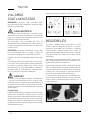
Tauchmotorpumpen der Baureihen U5 und
U6 eignen sich zur Förderung von häuslichem
Schmutzwasser ohne Steine. Hierzu zählt auch
das Schmutzwasser aus Haushalts-Wasch-
maschinen und Haushalts-Geschirrspülern.

4
DEUTSCH
Die U6K darf zusätzlich Grundwasser, Drainage-
wasser, Silagesaft und Flüssigdünger fördern.
HINWEIS! Im Freien dürfen nur Pumpen mit
mind. 10m Leitung eingesetzt werden.
Beim Einsatz der Pumpen müssen die jeweiligen
nationalen Gesetze, Vorschriften, sowie örtliche
Bestimmungen eingehalten werden, wie z.B.
•Häusliches Schmutz- und Abwasser
(z.B. in Europa EN 12056)
•Errichten von Niederspannungsanlagen
(z.B. in Deutschland VDE 0100)
Bei abweichenden Einsatzbedingungen sind wei-
tere Vorschriften zu beachten (z.B in Deutsch-
land VDE 0100, Teil 701: Bade- und Duschräume,
Teil 702: Schwimmbecken und Springbrunnen
und Teil 737: Einsatz im Freien).
Temperaturen
Das Fördermedium darf eine maximale Tempe-
ratur von 35° C haben.
Die Tauchpumpe ist bei Lagerung im Trocke-
nen bis -20º C frostsicher. Eingebaut darf sie im
Wasser jedoch nicht einfrieren.
Transport
Die Pumpe soll grundsätzlich am Tragegriff und
nicht am Anschlusskabel angehoben werden!
Das Versenken der Pumpe in tiefere Schächte
oder Gruben ist nur mit Seil oder Kette vorzu-
nehmen.
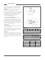
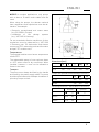
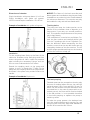
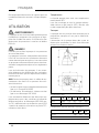
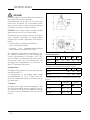
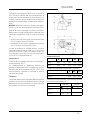
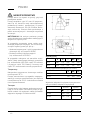
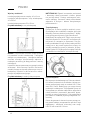
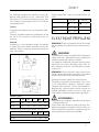
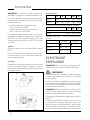
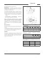
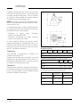
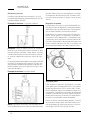
Maße [mm]
H B T BS TS
U5 K 280 170 250 205 290
U6 K 335 175 255 210 295
Pumpen mit Sonderschwimmer, (JP44207)
H BS TS
U5 KS 280 245 285
U6 KS 335 250 290
Schalthöhen Ein - Aus bei angebauter Schaltung
Normal Sonder
● ○ ● ○
U5 KS 240 135 90 40
U6 KS 270 170 130 80

5
DEUTSCH
ELEKTROANSCHLUSS
HINWEIS! Nur eine Elektro-Fachkraft darf an
Pumpe oder Steuerung Elektroarbeiten vorneh-
men.
WARNUNG!
Vor jeder Arbeit Pumpe und Steuerung vom Netz
trennen und sicherstellen, dass sie von anderen
Personen nicht wieder unter Spannung gesetzt
werden können.
Die jeweils gültigen Normen (z.B. EN), landes-
spezischen Vorschriften (z.B. VDE) sowie die
Vorschriften der örtlichen Versorgungsnetz-
betreiber sind zu beachten.
HINWEIS! Netzstecker oder freies Leitungsen-
de niemals ins Wasser legen! Eventuell eindrin-
gendes Wasser kann zu Störungen führen.
Betriebsspannung beachten (siehe Typenschild)!
Die Pumpe ist mit einem Wicklungsthermostaten
ausgestattet, der bei unzulässig hohen Tempe-
raturen die Pumpe abschaltet, bevor sie Scha-
den nehmen kann. Unzulässig hohe Temperatu-
ren können z.B. die Folge von Trockenlauf oder
mechanischer bzw. elektrischer Überlastung
sein.
VORSICHT!
Nach dem Abkühlen schaltet die Pumpe selbst-
tätig wieder ein – Verletzungsgefahr!
Daher vor dem Beseitigen der Störungsursache
die Pumpe immer spannungslos machen! Dazu
den Stecker aus der Steckdose ziehen bzw. die
Vorsicherungen der Pumpensteuerung heraus-
drehen!
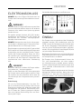
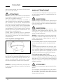
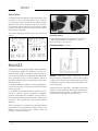
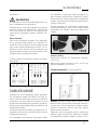
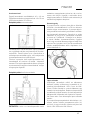
Drehrichtung
Gilt nur für Drehstrompumpen. Vor dem Ein-
bau ist die Drehrichtung zu prüfen! Bei richtiger
Drehrichtung erfolgt der Anlaufruck gegen den
Uhrzeigersinn. Bei falscher Drehrichtung müs-
sen 2 Phasen der Zuleitung getauscht werden,
denn eine falsche Drehrichtung führt zur Über-
lastung der Pumpe.
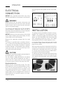
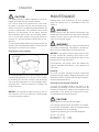
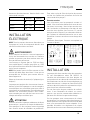
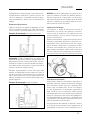
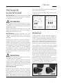
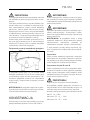
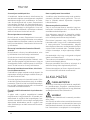
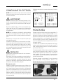
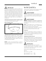
Schaltbilder Wechselstrom und Drehstrom
EINBAU
Die Pumpe muss entsprechend den Beispielen
eingebaut werden. Bei Installationen nach EN
12056-4 muss die Druckleitung als Schleife über
die örtlich festgelegte Rückstauebene geführt
und mit einem Rückussverhinderer gesichert
werden. Die mitgelieferte Gummiklappe (U5) wird
nur bei mobilem Betrieb benötigt.
Bei längerer Druckleitung ist zur Vermeidung von
Rohrreibungsverlusten ein entsprechend größe-
rer Rohrquerschnitt zu wählen.
Bei Pumpen ohne Schaltautomatik können die
Ein- und Ausschalthöhen mit einer separa-
ten Niveausteuerung variabel gesetzt werden.
Unsere steckerfertigen Niveausteuerungen sind
ohne spezielle elektrotechnische Kenntnisse
installierbar.
Das Pumpengehäuse wird automatisch über den
beiliegenden Winkel entlüftet. Wenn dies nicht
gewünscht ist, kann die Lüftungsöffnung ge-
schlossen werden, z.B. für den mobilen Betrieb.

6
DEUTSCH
Schachtmaße
Einzelanlage mit Standfuß: 40 x 40 cm
Einzelanlage mit Gleitrohr: 40 x 50 cm
Doppelanlage: 50 x 50 cm
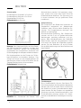
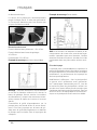
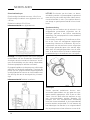
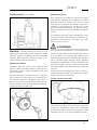
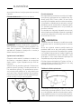
Einbaubeispiel mit Gleitrohr
Montage:
Den Kupplungsfuß fest auf dem Boden
des Sammelschachtes verdübeln und dann das
Gleitrohr montieren. Danach die Druckleitung
einschließlich der erforderlichen Armaturen wie
Rückschlagklappe und Absperrschieber einbauen.
Die Kupplungsklaue an der Pumpe mit Teon-
band eindichten und handfest anziehen. Zum
Schluß die Pumpe mit der Kupplungsklaue auf
das Gleitrohr setzen und mit einer Kette, die am
Tragegriff befestigt wird, hinunterlassen.
Einbaubeispiel Doppelanlage
HINWEIS! Die Schwimmer der Niveau- und
Alarmschaltung werden frei beweglich einge-
baut, jedoch nicht unter dem Zulauf. Bitte die
Mindestabstände beachten. Die Steuerung nur
in einem trockenen und gut gelüfteten Raum
installieren!
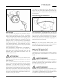
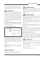
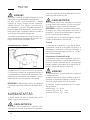
Spüleinrichtung
Die Pumpe kann den Boden des Schachtes im
Saugbereich weitgehend von Ablagerungen
freihalten, wenn Sie eine kleine Änderung vor-
nehmen. Die Pumpenleistung verringert sich
dadurch nur geringfügig.
Durchzuführende Änderung: Den Siebfuß ab-
nehmen und die 3 mit ø 5 gekennzeichneten
Markierungen vorsichtig aufbohren und ent-
graten. Beim Wiederaufrasten des Siebfußes
darauf achten, dass die neu gebohrten Löcher
nicht durch die Stege des Siebfußes verdeckt
werden. Bei den Baureihen U5 und U6 nden
Sie als Hilfe Markierungen auf dem Gehäuse und
dem Siebfuß.
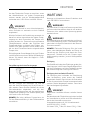
Flachabsaugen
Ohne Sonderzubehör können überutete Flä-
chen bis auf wenige mm Restwasser abgepumpt
werden, U5K: 6 mm und U6K: 10mm. Hierzu muss
der Siebfuß mit einem Schraubendreher abge-
hebelt werden. Bei den Pumpen mit angebauter
Schaltung muss der Schwimmerschalter in der
Einschaltstellung arretiert werden. Ein Schalt-
betrieb ist deshalb beim Flach saugen nicht mög-
lich.

7
DEUTSCH
Um das Fördern der Pumpe zu erreichen, muss
der Ablaufschlauch vor jedem Pumpvorgang
entleert werden und ein Mindestwasserstand
vorhanden sein, U5K: 60 mm und U6K: 90 mm.
VORSICHT!
Ein mobiler Betrieb ist aus sicherheitstech ni-
schen Gründen nur senkrecht und mit Siebfuß
zugelassen!
Wird ein Schlauch als Druckleitung verwandt, ist
darauf zu achten, dass dieser bei jedem Pump-
vorgang vor dem Eintauchen der Pumpe voll-
ständig entleert ist. Eventuell noch vorhandene
Flüssigkeitsreste würden das Entlüften des
Pumpengehäuses und damit das Fördern ver-
hindern. Aus dem gleichen Grund fördert auch
die vor dem Eintauchen bereits eingeschaltete
Pumpe nicht.
Die beiliegende Gummiklappe (nicht bei Flutbox
und U6) wird im montierten Winkel (U5) befestigt.
Achten Sie darauf, dass die Klappe in Fließ-
richtung öffnet.
Vergrößerung des freien Durchganges
Bei den Pumpen der Baureihen U5 und U6
kann der freie Durchgang von 10 auf 20 mm er-
höht werden. Dazu wird der Siebfuß mit einem
Schraubendreher abgehebelt und die bei-
liegenden Verlängerungen auf die angeformten
Pumpenfüße gesteckt. Der Siebfuß passt jetzt
nicht mehr unter die Pumpe.
HINWEIS! Bei einer defekten Pumpe kann ein
Teil der Ölkammerfüllung in das Fördermedium
entweichen.
WARTUNG
Wartung und Inspektion dieses Produktes sind
nach EN 12056-4 vorzunehmen.
WARNUNG!
Vor jeder Arbeit Pumpe und Steuerung vom Netz
trennen und sicherstellen, dass sie von anderen
Personen nicht wieder unter Spannung gesetzt
werden können.
WARNUNG!
Die Netzzuleitung auf mechanische und chemi-
sche Beschädigung prüfen. Beschädigte oder
geknickte Leitungen müssen durch den Herstel-
ler ersetzt werden.
HINWEIS! Fehlende Reinigung führt bei stark
eisen- oder kalkhaltigem Wasser auf Dauer zur
Zerstörung der Dichtung und damit des Pum-
penmotors. Deshalb muss die Pumpe regel-
mäßig gereinigt werden, je nach Härtegrad des
Wassers.
Reinigung
Der Siebfuß verhindert das Eindringen grober Ver-
unreinigungen in die Pumpe. Regelmäßiges Reini-
gen des Schwimmers und des Siebfußes sichert
die maximal mögliche Leistung und Funktion.
Reinigung des Laufrades U5 und U6
Zur Reinigung des Laufrades, bei Blockierung
oder Verstopfung, muss zuerst der Siebfuß
abgehebelt werden. Dann können die Schrauben
an der Unterseite der Pumpe herausgeschraubt
und der Deckel abgezogen werden. Jetzt kann
das Laufrad gereinigt werden.
VORSICHT!
Abgenutzte Laufräder können scharfe Kanten
haben.
Bei abnehmender Förderleistung ist das Laufrad
auf Verschleiss zu prüfen und, falls erforderlich,
durch den Hersteller zu erneuern.
Anzugsdrehmomente MA für Schraubenwerk-
stoff A2 für M 5 MA = 5 Nm ,
für Amtec 3,5 MA = 1 Nm, für Amtec 5,0 MA = 2 Nm

8
DEUTSCH
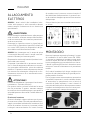
KLEINE HILFE BEI
STÖRUNGEN
Pumpe läuft nicht
•Netzspannung prüfen (keinen Prüfstift ver-
wenden)
•Sicherung defekt = eventuell zu schwach
(siehe Elektro-Anschluss)
•Netzzuleitung beschädigt = Reparatur nur
durch den Hersteller
Pumpe läuft, aber fördert nicht
•Druckleitung bzw. Schlauch entleeren, damit
die Rückschlagklappe öffnet und die Luft aus
dem Pumpengehäuse entweichen kann, evtl.
eine Entlüftungsbohrung anbringen
Laufrad blockiert
•Fest- und Faserstoffe haben sich im Pumpen-
gehäuse festgesetzt = reinigen
Verminderte Förderleistung
•Siebfuß verstopft = reinigen
•Druckleitung verstopft = reinigen
•Laufrad verschlissen = Reparatur nur durch
den Hersteller
•Falsche Drehrichtung (bei Drehstrom) =
2 Phasen der Zuleitung von einer Elek-
trofachkraft tauschen lassen
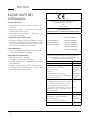
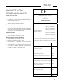
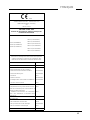
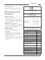
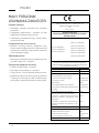
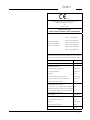
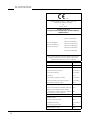
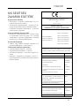
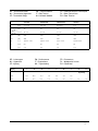
0197
JUNG PUMPEN GmbH - Industriestr. 4-6
33803 Steinhagen, Germany
20
401.17-22.02
EN 12050-2:2001; 2015
Abwasserhebeanlage für fäkalienfreies Abwasser DN 32
U5 K (JP09386/0)
U5 KS (JP09387/0)
U5 KS (JP09417/0)
U6 K E (JP00226/2)
U6 K D (JP00228/3)
U6 K ES (JP00227/2)
U6 K ES (JP09260/2)
U6 K DS (JP00229/3)
U6 K DS (JP09261/3)
Sammeln und automatisches Heben von fäkalien-
freiem Abwasser innerhalb und außerhalb von
Gebäuden über die Rückstauebene
BRANDVERHALTEN NPD
WASSERDICHTHEIT Bestanden
WIRKSAMKEIT (HEBEWIRKUNG)
- Förderung von Feststoffen Bestanden
- Rohranschlüsse Bestanden
- Lüftung NPD
- Mindestießgeschwindigkeit Bestanden
-
Freier Mindestdurchgang der Anlage
Bestanden
- Mindestnutzvolumen NPD
MECHANISCHE FESTIGKEIT
- Tragfähigkeit und strukturelle Stabili-
tät des Sammelbehälters für die Ver-
wendung außerhalb von Gebäuden
NPD
- Strukturelle Stabilität des Sammel-
behälters für die Verwendung inner-
halb von Gebäuden
NPD
GERÄUSCHPEGEL 70 dB(A)
DAUERHAFTIGKEIT
- der Wasser- und Luftdichtheit NPD
- der Hebewirkung Bestanden
- der mechanischen Festigkeit NPD
GEFÄHRLICHE SUBSTANZEN NPD

9 9
ENGLISH
You have purchased a product made by
JUNG PUMPEN and with it, therefore, also
excellent quality and service. Secure this
service by carrying out the installation
works in accordance with the instruc-
tions, so that our product can perform
its task to your complete satisfaction.
Please remember that damage caused
by incorrect installation or handling will
adversely affect the guarantee. There-
fore please adhere to the instructions in
this manual!
This appliance can be used by children
aged 8 years or over and by persons with
limited physical, sensory or intellectual
capabilities, or with limited experience
and knowledge, provided that they are
supervised or have been instructed in
the safe use of the appliance and are
aware of the dangers involved. Children
must not be allowed to play with the ap-
pliance. Cleaning and user maintenance
must not be carried out by children un-
less they are supervised.
Damage prevention in case of failure
Like any other electrical device, this product
may fail due to a lack of mains voltage or a tech-
nical defect.
If damage (including consequential damage) can
occur as a result of product failure, the following
precautions can be taken at your discretion:
•Installation of a water level dependent (under
circumstances, mains-independent) alarm
system, so that the alarm can be heard before
damage occurs.
•Inspection of the collecting tank/chamber for
tightness up to the top edge before – or at the
latest, during – installation or operation of the
product.
•Installation of backow protection for drain-
age units that can be damaged by wastewater
leakage upon product failure.
•Installation of a further product that can com-
pensate in case of failure of the other product
(e.g. duplex unit).
•Installation of an emergency power genera-
tor.
As these precautions serve to prevent or mini-
mise consequential damage upon product fail-
ure, they are to be strictly observed as the man-
ufacturer’s guideline – in line with the standard
DIN EN specications as state of the art – when
using the product (Higher Regional Court Frank-
furt/Main, Ref.: 2 U 205/11, 06/15/2012).
SAFETY INSTRUCTIONS
This instruction manual contains essential in-
formation that must be observed during instal-
lation, operation and servicing. It is therefore
important that the installer and the responsible
technician/operator read this instruction manu-
al before the equipment is installed and put into
operation. The manual must always be available
at the location where the pump or the plant is
installed.
Failure to observe the safety instructions can
lead to the loss of all indemnity.
In this instruction manual, safety information is
distinctly labelled with particular symbols. Dis-
regarding this information can be dangerous.
General danger to people
Warning of electrical voltage
NOTICE! NOTICE!
Danger to equipment and operation
Qualication and training of personnel
All personnel involved with the operation, ser-
vicing, inspection and installation of the equip-
ment must be suitably qualied for this work
and must have studied the instruction manual
in depth to ensure that they are suciently
conversant with its contents. The supervision,
competence and areas of responsibility of the
personnel must be precisely regulated by the

10 10
ENGLISH
operator. If the personnel do not have the ne-
cessary skills, they must be instructed and trai-
ned accordingly.
Safety-conscious working
The safety instructions in this instruction man-
ual, the existing national regulations regarding
accident prevention, and any internal working,
operating and safety regulations must be ad-
hered to.
Safety instructions for the operator/user
All legal regulations, local directives and safety
regulations must be adhered to.
The possibility of danger due to electrical en-
ergy must be prevented.
Leakages of dangerous (e.g. explosive, toxic,
hot) substances must be discharged such that
no danger to people or the environment occurs.
Legal regulations must be observed.
Safety instructions for installation, inspection
and maintenance works
As a basic principle, works may only be car-
ried out to the equipment when it is shut down.
Pumps or plant that convey harmful substances
must be decontaminated.
All safety and protection components must be
re-tted and/or made operational immediately
after the works have been completed. Their ef-
fectiveness must be checked before restarting,
taking into account the current regulations and
stipulations.
Unauthorised modications, manufacture of
spare parts
The equipment may only be modied or altered
in agreement with the manufacturer. The use of
original spare parts and accessories approved
by the manufacturer is important for safety rea-
sons. The use of other parts can result in liability
for consequential damage being rescinded.
Unauthorised operating methods
The operational safety of the supplied equip-
ment is only guaranteed if the equipment is
used for its intended purpose. The limiting val-
ues given in the "Technical Data" section may not
be exceeded under any circumstances.
Instructions regarding accident prevention
Before commencing servicing or maintenance
works, cordon off the working area and check
that the lifting gear is in perfect condition.
Never work alone. Always wear a hard hat, safety
glasses and safety shoes and, if necessary, a
suitable safety belt.
Before carrying out welding works or using elec-
trical devices, check to ensure there is no dan-
ger of explosion.
People working in wastewater systems must be
vaccinated against the pathogens that may be
found there. For the sake of your health, be sure
to pay meticulous attention to cleanliness wher-
ever you are working.
Make sure that there are no toxic gases in the
working area.
Observe the health and safety at work regula-
tions and make sure that a rst-aid kit is to hand.
In some cases, the pump and the pumping me-
dium may be hot and could cause burns.
For installations in areas subject to explosion
hazards, special regulations apply!
APPLICATION
WARNING!
The pump must only be connected to sockets
that have been installed properly in accordan-
ce with the regulations and are protected with
at least 10 A (slow) and RCD-safety switches
(30mA).
DANGER!
The pump must never be used when a person is
in the water.
Submersible pumps from the U5 and U6 series
are suitable for pumping domestic waste water
without stones. This includes also water from
household dishwashers and household washing
machines.
The U6 can also pump ground water, drainage
silage liquor and liquid manure.

11 11
ENGLISH
NOTICE! In outdoor applications, only pumps
with at least a 10-metre mains cable must be
used.
When using the pumps, the relevant national
laws, regulations and stipulations must be ad-
hered to, for example:
•Domestic contaminated and waste water
(e.g. EN 12056 in Europe)
•Installation of low voltage systems
(e.g., VDE 0100 in Germany)
For non-standard utilization conditions, further
regulations must be observed (e.g. VDE 0100
in Germany, part 701: bathrooms and shower
rooms; part 702: swimming pools and fountains
and part 737: outdoor use).
Temperatures
The pumped medium must have a temperature
of max 35°C.
The submersible pump is frost-resistant down
to -20°C when stored in dry conditions. When
installed, however, it must not be allowed to
freeze in the water.
Transport
The pump must always be lifted by the handle
and never by the power supply cable! The pump
should only be lowered into deeper chambers or
pits using a rope or chain.
Dimensions [mm]
H B T BS TS
U5 K 280 170 250 205 290
U6 K 335 175 255 210 295
Pumps with special oat assembly, (JP44207)
H BS TS
U5 KS 280 245 285
U6 KS 335 250 290
Switching points On - Off for built-in switching
Normal Special
● ○ ● ○
U5 KS 240 135 - -
U6 KS 270 170 - -

12 12
ENGLISH
ELECTRICAL
CONNECTION
NOTICE! Only qualied electricians may carry
out electrical works to the pump or the controls.
WARNING!
Before carrying out any works: disconnect the
pump and the controls from the mains and take
steps to ensure that no one else can reconnect
them to the power supply.
The relevant standards (such as EN standards),
country-specic regulations (such as VDE in
Germany), and the regulations of the local power
supply companies must be observed.
NOTICE! Never put the mains plug or a free lead
end in water! If water gets into the plug, this can
cause malfunctions and damage.
Observe the operating voltage (see the type
plate)!
The pump is provided with a winding thermo-
stat. In case of unacceptably high temperatures
it switches off the pump to protect it against
possible damage. Unacceptably high tempera-
tures may result e.g. from dry running or me-
chanical or electrical overload.
CAUTION!
The pump is switched on again automatically af-
ter cooling down - risk of injury!
For this reason, always disconnect the device
from the mains before remedying the fault! In
order to do this, unplug from the mains supply
or remove the pre-fuses of the pump controls!
Rotational direction
Applies only for three-phase pumps. The rota-
tional direction must be checked before instal-
lation! If the rotational direction is correct, the
start-up jolt should be counter-clockwise. If the
rotational direction is wrong, 2 phases of the
supply cable must be swapped over, because a
wrong direction of rotation results in an over-
load of the pump.
Alternating and three-phase current circuit dia-
grams
INSTALLATION
The pump must be installed as shown in the ex-
amples. For installations in accordance with EN
12056-4, the pressure pipe must be laid in a loop
above the local backow level and protected
with a backow prevention valve. The rubber
ap supplied (U5) is for mobile operation only.
A correspondingly larger diameter pipe should
be used for longer pressure pipelines to avoid
pipe friction losses.
With any pump that has no automatic switching,
the switch-on and switch-off heights can be set
variably with a separate level control. Our ready
to connect level controls can be installed with-
out specic electrotechnical skills.
The pump housing is automatically vented using
the enclosed bracket. If this is not required, the
vent opening can be closed, such as for mobile
operation.

13 13
ENGLISH
Dimensions of chamber
Single installation with pump base: 40 x 40 cm
Single installation with guide rail system:
40 x 50 cm and Duplex installation: 50 x 50 cm
Example of installation with guide rail system
Installation
Fix the coupling base rmly to the oor of the
collection chamber using wall plugs and then
mount the guide rail. Next, install the pressure
pipe including the necessary ttings, such as
the non-return valve and shut-off valves.
Reseal the coupling catch at the pump and
tighten it until it is “hand tight”. Finally, t the
pump with the coupling catch onto the guide rail
and lower it into place using a chain xed to the
handle.
Example of installation Duplex unit
NOTICE! The oats of the level controller and
alarm system are installed so that they are freely
movable but not under the inlet. Please observe
the minimum distances. The controls may only
be installed in a dry and well ventilated room!
Flushing device
The pump can keep the intake section at the
bottom of the chamber clear of deposits to a
large extent if you carry out a small modica-
tion. This reduces the performance of the pump
only insignicantly.
This modication is carried out as follows. De-
tach the foot strainer and carefully drill a hole
into the 3 markings with the ø 5 symbols. De-
burr the drillholes. When reattaching the foot
strainer, ensure that the new drill-holes are not
covered by the bars of the foot strainer. The U5
and U6 ranges provide markings on the housing
and the foot strainer to help you.
Low level pumping
Flooded areas can be pumped out leaving only
few mm of residual water without the need for
optional extras, U5K: 6 mm and U6K: 10 mm. To
do so, the foot strainer must be levered off with
a screwdriver. In the case of pumps with an at-
tached control, the oat switch must be locked
in the ON position. It is not possible therefore
in low level pumping to operate the pump in
switching mode.
To make the pump operate, the drainage hose
must be emptied before each pumping run and
there must be a minimum water level available of,
for U5K: 60 mm and for U6K: 90 mm.

14 14
ENGLISH
CAUTION!
For safety reasons, mobile operation is only al-
lowed vertically and with a foot strainer!
If a hose is used as a pressure line, care must
be taken to ensure that for every pumping op-
eration the hose is completely empty before the
pump is submersed. Any residual liquid would
obstruct the ventilation of the pump housing
and therefore also hinder the pumping opera-
tion. For the same reason, the pump would not
operate if it was switched on before being sub-
mersed.
The enclosed rubber ap (not Flutbox and U6) is
tted in the attached elbow (U5). Ensure that the
ap opens in the direction of ow.
Enlarging the free passage
The free passage of the U5 and U6 pump ranges
can be enlarged from 10 to 20 mm. This is done
by levering off the foot strainer and attaching
the enclosed extensions to the integrally mold-
ed pump feet. The foot strainer no longer ts
under the pump.
NOTICE! If the pump is malfunctioning, part of
the contents of the oil reservoir could escape
into the pumping medium.
MAINTENANCE
Maintenance and inspection of this product
must be carried out in accordance with EN
12056-4.
WARNING!
Before carrying out any works: disconnect the
pump and the controls from the mains and take
steps to ensure that no one else can reconnect
them to the power supply.
WARNING!
Check the mains cable for signs of mechanical
and chemical damage. Damaged or kinked ca-
bles must be replaced by the manufacturer.
NOTICE! If the water contains high levels of iron
or lime, insucient cleaning can result in irre-
parable damage to the seal and thus also to the
pump motor in the long term.
Consequently, the pump must be cleaned at
regular intervals according to the hardness of
the water.
Cleaning
The foot strainer prevents coarse impurities
from entering the pump. Regular cleaning of the
oat and the foot strainer ensures optimum per-
formance and operation.
Cleaning of the impeller U5 and U6
To clean the impeller, and in the event of an
obstacle or blockage, the foot strainer must be
levered off. After this, take out the screws on the
underside of the pump and remove the cover.
The impeller can now be cleaned.
CAUTION!
Worn impellers can have sharp edges.
If the pump performance decreases, the impel-
ler must be checked for wear and replaced only
by the manufacturer if necessary.
Tightening torque MAfor A2 screw materials
for M 5 MA = 5 Nm
for Amtec 3,5 MA = 1 Nm
for Amtec 5,0 MA = 2 Nm

15 15
ENGLISH
QUICK TIPS FOR
REMEDYING FAULTS
Pump does not work
•Check mains current (do not use a pin gauge)
•Fuse faulty = may be too weak (please refer to
Electrical Connection)
•Mains supply cable damaged = repair to be
carried out by manufacturer only
Pump runs but does not pump
•Empty the pressure pipe or hose to allow the
non-return valve to open and the air to escape
from the pump housing, it may be necessary
to carry out a ventilation drilling
Impeller blocked
•Solids and brous matter have become lod-
ged in the pump housing = clean
Decreased pumping performance
•Foot strainer obstructed = clean
•Pressure pipe obstructed = clean
•Rotor worn out = repair to be carried out by
the manufacturer
•Wrong direction of rotation (for a three-pha-
se current) = ask a qualied electrician to
change 2 phases of the supply line
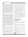
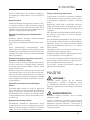
0197
JUNG PUMPEN GmbH - Industriestr. 4-6
33803 Steinhagen, Germany
20
401.17-22.02
EN 12050-2:2001; 2015
Lifting plant for faecal-free wastewater DN 32
U5 K (JP09386/0)
U5 KS (JP09387/0)
U5 KS (JP09417/0)
U6 K E (JP00226/2)
U6 K D (JP00228/3)
U6 K ES (JP00227/2)
U6 K ES (JP09260/2)
U6 K DS (JP00229/3)
U6 K DS (JP09261/3)
Collecting and automatically lifting faecal-free
waste water above the backow level in buildings
and sites
REACTION TO FIRE NPD
WATERTIGHTNESS Pass
EFFECTIVENESS (LIFTING EFFECT
- Pumping of solids Pass
- Pipe connections Pass
- Ventilation NPD
- Minimum ow velocity Pass
-
Minimum free passage of the plant
Pass
- Minimum useful volume NPD
MECHANICAL RESISTANCE
- Load bearing capacity and structural
stability of collection tank for use
NPD
- Structural stability of collection tank
for use inside buildings
NPD
NOISE LEVEL 70 dB(A)
DURABILITY
- of structural stability NPD
- of lifting effectiveness Pass
- of mechanical resistance NPD
DANGEROUS SUBSTANCES NPD

16 16
FRANÇAIS
Vous avez opté pour un produit JUNG
PUMPEN, synonyme de qualité et de
performance. Assurez-vous cette per-
formance par une installation conforme
aux directives: notre produit pourra
ainsi remplir sa mission à votre entière
satisfaction. N‘oubliez pas que les dom-
mages consécutifs à un maniement non
conforme porteront préjudice au droit à
la garantie. Veuillez donc respecter les
consignes contenues dans ces instruc-
tions !
Cet appareil peut être utilisé par des
enfants d'au moins 8 ans ainsi que par
les personnes ayant des capacités phy-
siques, sensorielles ou mentales limi-
tées ou qui manquent d'expérience et de
connaissance, dans la mesure où ils sont
surveillés ou s'ils ont reçu des instruc-
tions pour une utilisation en toute sécu-
rité de l'appareil et qu'ils comprennent
les risques qui en résultent. Les enfants
ne doivent pas jouer avec l'appareil. Le
nettoyage et l'entretien de l'appareil
ne doivent pas être effectués par des
enfants si ceux-ci ne sont pas sous sur-
veillance.
Prévention des dommages en cas de défail-
lance
Comme tout autre appareil électrique, ce pro-
duit peut aussi tomber en panne suite à une
absence de tension ou à un défaut technique.
Si un dommage (également dommage consé-
cutif) se produit en raison de la défaillance du
produit, les dispositions suivantes doivent être
prise en particulier selon votre appréciation :
•Montage d’une alarme en fonction du niveau
d’eau (éventuellement aussi indépendante du
réseau électrique) de sorte que l’alarme pu-
isse être perçue avant l’apparition d’un dom-
mage.
•Contrôle de l’étanchéité du réservoir collec-
teur / cuve utilisée jusqu’au bord supérieur
avant - toutefois au plus tard- le montage ou
la mise en service du produit.
•Montage de protection anti-retour pour les
objets de drainage sur lesquels un domma-
ge peut survenir par l’écoulement d’eau usée
après une défaillance du produit.
•Montage d’un autre produit pouvant compen-
ser la défaillance du produit (par ex. poste
double).
•Montage d’un groupe de secours.
Étant donné que ces dispositions servent à
prévenir ou réduire les dommages consécutifs
à une défaillance du produit, elles sont obli-
gatoires en tant que disposition du fabricant
au même titre que les contraintes normatives
de la FR EN comme état de la technique lors
de l’utilisation du produit (OLG Francfort/Main,
n°dossier: 2 U 205/11, 15.06.2012).
CONSIGNES DE
SÉCURITÉ
Ces instructions de service contiennent des
informations essentielles à respecter lors de
l‘installation, de la mise en service et de la main-
tenance.
Il est impératif que le monteur et l‘exploitant/ le
personnel qualié concernés lisent les instruc-
tions de service avant le montage et la mise en
service.
Les instructions doivent toujours être dispo-
nibles sur le lieu d‘utilisation de la pompe ou de
l‘installation.
Le non respect des consignes de sécurité peut
entraîner la perte de tous les droits à réparation
du dommage.
Dans ces instructions de service, les consignes
de sécurité sont identiées de manière particu-
lière par des symboles.
Risque d‘ordre général pour les per-
sonnes

17 17
FRANÇAIS
Avertissement contre la tension élec-
trique
AVIS! AVIS! Danger pour la machine et le fonctionne-
ment
Qualication du personnel
Le personnel pour le maniement, la mainte-
nance, l‘inspection et le montage doit posséder
la qualication nécessaire à ce type de travaux
et il doit s‘être susamment bien informé par
une étude approfondie des instructions de ser-
vice.
Domaine de responsabilité, l‘exploitant doit ré-
gler avec précision la compétence et le contrôle
du personnel.
Si le personnel ne possède pas les connais-
sances nécessaires, il est impératif de le former
et de l‘instruire.
Travailler en étant soucieux de la sécurité
Il est impératif de respecter les consignes de
sécurité, les règlements nationaux en vigueur
concernant la prévention des accidents et les
prescriptions internes éventuelles de travail, de
service et de sécurité contenus dans ces ins-
tructions.
Consignes de sécurité pour l‘exploitant/
l‘utilisateur
Les directives légales, les règlements locaux et
les directives de sécurité doivent être respec-
tés.
Il faut exclure les risques dus à l‘énergie élec-
trique.
Les fuites de matières dangereuses à refouler
(explosives, toxiques ou brûlantes par exemple)
doivent être évacuées de telle sorte qu‘elles ne
représentent aucun danger pour les personnes
et l‘environnement. Les directives légales en
vigueur sont à respecter.
Consignes de sécurité pour le montage, les
travaux d‘inspection et de maintenance
D‘une manière générale, les travaux à effectuer
devront l‘être exclusivement sur une machine à
l‘arrêt. Les pompes ou agrégats refoulant des
matières dangereuses pour la santé doivent
être décontaminés.
Directement après la n des travaux, tous les
dispositifs de sécurité et de protection doivent
être remis en place ou en service. Leur eca-
cité est à contrôler avant la remise en service et
en tenant compte des directives et règlements
en vigueur.
Transformation et fabrication de pièces déta-
chées sans concertation préalable
Une transformation ou une modication de
la machine est uniquement autorisée après
consultation du fabricant. Les pièces déta-
chées d‘origine et les accessoires autorisés par
le fabricant servent à la sécurité. L‘utilisation
d‘autres pièces peut annuler la responsabilité
quant aux conséquences en résultant.
Formes de service interdites
La sécurité d‘exploitation de la machine livrée
est uniquement garantie lors d‘une utilisation
conforme. Il est absolument interdit de dépas-
ser les valeurs limites indiquées au chapitre «
Caractéristiques technique «.
Consignes concernant la prévention des
accidents
Avant les travaux de montage ou de mainte-
nance, barrer la zone de travail et contrôler le
parfait état de l‘engin de levage.
Ne jamais travailler seul et utiliser un casque,
des lunettes protectrices et des chaussures de
sécurité, ainsi qu‘en cas de besoin, une ceinture
de sécurité adaptée.
Avant d‘effectuer des soudures ou d‘utiliser
des appareils électriques, vériez l‘absence de
risque d‘explosion.
Les personnes travaillant dans des infrastruc-
tures d‘assainisse ment doivent être vaccinées
contre les agents pathogènes pouvant éventuel-
lement s‘y trouver. D‘autre part, veiller scrupuleu-
sement à l‘hygiène, par égard pour votre santé.
Assurez-vous qu‘aucun gaz toxique ne se trouve
dans la zone de travail.
Respectez les règlements concernant la sécu-
rité de travail et gardez le nécessaire de premier
secours à portée de main.
Dans certains cas, la pompe et le produit
peuvent être brûlants, il y a alors risque de brû-
lure.

18 18
FRANÇAIS
Des règles spéciales entrent en vigueur pour les
installations dans les secteurs à risque d‘explo-
sion!
UTILISATION
AVERTISSEMENT !
La pompe ne doit être raccordée qu'à des prises
installées en respectant les consignes et équi-
pées d'un fusible d'au moins 10 A (inerte) et d'un
disjoncteur de protection à courant de défaut
(30 mA).
DANGER !
Il ne faut pas utiliser la pompe si une personne
se trouve dans l’eau.
Les pompes à moteur submersibles des séries
U5 et U6 conviennent au refoulement des eaux
usées domestiques sans pierre. Les eaux usées
en provenance des machines à laver et des lave-
vaisselle à usage domestique en font également
partie.
Lors de l'utilisation des pompes, il est néces-
saire d'observer les différentes lois nationales,
les directives ainsi que les dispositions locales,
comme par ex.
AVIS! Seules les pompes avec un câble de rac-
cordement d'au moins 10 m peuvent être utili-
sées à l'extérieur.
•les eaux usées et eaux chargées domestiques
(par ex. in Europa EN 12056)
•la réalisation d'installations à basse tension
(par ex. en Allemagne VDE 0100)
Il est nécessaire d'observer des directives sup-
plémentaires pour des conditions d'utilisation
différentes (par ex. en Allemagne VDE 0100, par-
tie 701 : salles de bains et de douche, partie 702
: bassins de natation et fontaines et partie 737 :
utilisation à l'air libre).
Températures
Le liquide pompé peut avoir une température
maximale de 35°C.
Lors d'un stockage au sec, la pompe submer-
sible résiste au gel jusqu'à -20°C. Montée, elle
ne doit cependant pas geler dans l'eau.
Transport
La pompe doit en principe être soulevée par la
poignée de transport et non par le câble d'ali-
mentation !
L'immersion de la pompe dans des cuves ou
fosses plus profondes ne doit être effectuée
qu'avec une corde ou chaîne.
Dimensions [mm]
H B T BS TS
U5 K 280 170 250 205 290
U6 K 335 175 255 210 295
Pompes avec otteur spécial, (JP44207)
H BS TS
U5 KS 280 245 285
U6 KS 335 250 290

19 19
FRANÇAIS
Hauteurs d'enclenchement Marche-Arrêt avec
commande intégrée
Normal Special
● ○ ● ○
U5 KS 240 135 - -
U6 KS 270 170 - -
INSTALLATION
ÉLECTRIQUE
AVIS! Tous les travaux de nature électrique sur
la pompe ou l'unité de commande doivent être
conés à un électricien conrmé.
AVERTISSEMENT !
Avant chaque intervention : mettre la pompe et
l'unité de commande hors tension et s'assurer
qu'elles ne peuvent pas être remises sous ten-
sion par d'autres personnes.
Les normes en vigueur (par ex. EN), les direc-
tives spéciques à chaque pays (par ex. VDE)
ainsi que les directives local du réseau d'alimen-
tation sont à respecter.
AVIS ! Ne jamais mettre la che secteur ou l'ex-
trémité de câble libre dans l'eau ! L'eau qui est
susceptible de s'inltrer peut causer des en-
dommagements.
Observer la tension de service (cf. plaque signa-
létique) !
La pompe est équipée d'un thermostat à enrou-
lement qui arrête la pompe en cas de tempéra-
tures élevées non autorisées avant que celle-ci
ne puisse être endommagée. Des températures
élevées non autorisées peuvent être notam-
ment causées par une marche à sec ou une sur-
charge mécanique ou électrique.
ATTENTION!
Une fois refroidie, la pompe redémarre de façon
automatique - attention au risque de blessures !
C'est pourquoi, il faut toujours mettre la pompe
hors tension avant de remédier au problème !
Pour cela, retirer la che de la prise de courant
ou ôter les fusibles de puissance de l'unité de
commande de la pompe !
Sens de rotation
Vaut uniquement pour les pompes à courant tri-
phasé. Il est nécessaire d'observer le sens de rota-
tion avant le montage ! Avec le bon sens de rota-
tion, la réaction au démarrage a lieu dans le sens
contraire des aiguilles d'une montre. En cas de
sens de rotation inversé, il est nécessaire d'échan-
ger 2 phases du câble d'alimentation car un sens
de rotation incorrect entraîne une surcharge de la
pompe.
Schémas électriques Courant monophasé et
Courant triphasé
INSTALLATION
La pompe doit être montée selon les exemples.
En cas d'installations selon EN 12056-4, la
conduite de refoulement doit être dirigée, en
tant que boucle, au-dessus du niveau de retenue
xé localement et elle doit être protégée par un
clapet de retenue. Le clapet en caoutchouc (U5)
contenu dans la livraison est nécessaire unique-
ment lors d'une utilisation mobile.
En cas d'une plus longue conduite de refoule-
ment, il est nécessaire de choisir, en consé-
quence, une section transversale tubulaire su-
périeure an d'éviter les pertes de charge.
Sur les pompes sans commutateur de niveau
automatique, les hauteurs d'enclenchement et
d'arrêt peuvent être réglées de manière variable
avec une commande de niveau séparée. Il est
possible d'installer nos régulateurs de niveau
prêts à brancher sans connaissance particulière

20 20
FRANÇAIS
en électrotechnique.
Le carter de la pompe est automatiquement
purgé via l’angle fourni. Si cela n’est pas souhai-
té, l’ouverture d’aération peut être fermée, par
ex. pour l’utilisation mobile.
Dimensions de la cuve
Poste individuel avec piètement : 40 x 40 cm
Posteindividuel avec barre de guidage :
40 x 50 cm
Postedouble : 50 x 50 cm
Exemple de montage avec barre de guidage
Montage : Cheviller fermement le pied d'assise
au sol de la chambre collectrice et monter la
barre de guidage. Monter ensuite la conduite
de refoulement y compris les armatures néces-
saires comme le clapet anti-retour et la vanne
d'arrêt.
Etanchéier la griffe d'accouplement sur la
pompe avec une bande téon et serrer ferme-
ment. Puis xer la pompe sur la barre de gui-
dage avec la griffe d'accouplement et abaisser
la pompe avec la chaîne xée à la poignée de
transport.
Exemple de montage Poste double
AVIS ! Les otteurs du dispositif d'alarme et du
commutateur de niveau sont montés de façon
mobile, cependant pas sous l'amenée. Veuillez
observer les écarts minimum. Installer l'unité de
commande dans une pièce sèche et bien venti-
lée !
Prise de rinçage
La pompe peut considérablement empêcher la
présence de dépôts dans le fond de la cuve dans
la zone d'aspiration si vous effectuez une légère
modication. La performance de la pompe ne
diminue que légèrement.
Modication à effectuer : ôter le pied perforé
et percer ainsi qu'ébavurer avec précaution
les 3 marquages caractérisés par ø 5. Lors de
la remise en place du pied perforé, veillez à ce
que les trous venant d'être percés ne soient pas
cachés par les xations du pied perforé. Pour les
séries U5 et U6, les marquages sur le boîtier ain-
si que sur le pied perforé vous serviront d'aide.
Strona się ładuje...
Strona się ładuje...
Strona się ładuje...
Strona się ładuje...
Strona się ładuje...
Strona się ładuje...
Strona się ładuje...
Strona się ładuje...
Strona się ładuje...
Strona się ładuje...
Strona się ładuje...
Strona się ładuje...
Strona się ładuje...
Strona się ładuje...
Strona się ładuje...
Strona się ładuje...
Strona się ładuje...
Strona się ładuje...
Strona się ładuje...
Strona się ładuje...
Strona się ładuje...
Strona się ładuje...
Strona się ładuje...
Strona się ładuje...
Strona się ładuje...
Strona się ładuje...
Strona się ładuje...
Strona się ładuje...
Strona się ładuje...
Strona się ładuje...
Strona się ładuje...
Strona się ładuje...
Strona się ładuje...
Strona się ładuje...
Strona się ładuje...
Strona się ładuje...
Strona się ładuje...
Strona się ładuje...
Strona się ładuje...
Strona się ładuje...
Strona się ładuje...
Strona się ładuje...
Strona się ładuje...
Strona się ładuje...
Strona się ładuje...
Strona się ładuje...
Strona się ładuje...
Strona się ładuje...
Strona się ładuje...
Strona się ładuje...
Strona się ładuje...
Strona się ładuje...
Strona się ładuje...
Strona się ładuje...
Strona się ładuje...
Strona się ładuje...
-
 1
1
-
 2
2
-
 3
3
-
 4
4
-
 5
5
-
 6
6
-
 7
7
-
 8
8
-
 9
9
-
 10
10
-
 11
11
-
 12
12
-
 13
13
-
 14
14
-
 15
15
-
 16
16
-
 17
17
-
 18
18
-
 19
19
-
 20
20
-
 21
21
-
 22
22
-
 23
23
-
 24
24
-
 25
25
-
 26
26
-
 27
27
-
 28
28
-
 29
29
-
 30
30
-
 31
31
-
 32
32
-
 33
33
-
 34
34
-
 35
35
-
 36
36
-
 37
37
-
 38
38
-
 39
39
-
 40
40
-
 41
41
-
 42
42
-
 43
43
-
 44
44
-
 45
45
-
 46
46
-
 47
47
-
 48
48
-
 49
49
-
 50
50
-
 51
51
-
 52
52
-
 53
53
-
 54
54
-
 55
55
-
 56
56
-
 57
57
-
 58
58
-
 59
59
-
 60
60
-
 61
61
-
 62
62
-
 63
63
-
 64
64
-
 65
65
-
 66
66
-
 67
67
-
 68
68
-
 69
69
-
 70
70
-
 71
71
-
 72
72
-
 73
73
-
 74
74
-
 75
75
-
 76
76


w innych językach
- italiano: Pentair U5 K Manuale utente
- Deutsch: Pentair U5 K Benutzerhandbuch
- slovenčina: Pentair U5 K Používateľská príručka
- français: Pentair U5 K Manuel utilisateur
- Nederlands: Pentair U5 K Handleiding
- română: Pentair U5 K Manual de utilizare