ELICA PRF0183203 Built In Hood Cm 60 Instrukcja obsługi
- Typ
- Instrukcja obsługi

INSTALLATION, USE AND MAINTENANCE INSTRUCTION
ISTRUZIONI PER INSTALLAZIONE, USO E MANUTENZIONE
INSTRUCTIONS POUR L’INSTALLATION, L’UTILISATION ET L’ENTRETIEN
INSTRUCCIONES PARA LA INSTALACIÓN USO Y MANTENIMIENTO
INSTRUKCJE MONTAŻU, UŻYTKOWANIA I KONSERWACJI
ANLEITUNG ZUR INSTALLATION, INBETRIEBNAHME UND WARTUNG
INSTRUCTIES VOOR INSTALLATIE, GEBRUIK EN ONDERHOUD
ІНСТРУКЦІЇ З МОНТАЖУ, ЕКСПЛУАТАЦІЇ ТА ТЕХНІЧНОГО ОБСЛУГОВУВАННЯ
РУКОВОДСТВО ПО УСТАНОВКЕ, ЭКСПЛУАТАЦИИ И ТЕХОБСЛУЖИВАНИЮ
PRF0183203
PRF0183209
PRF0183210
PRF0183213
PRF0183218
PRF0183219

2

1
3
2
3 4
56

7
4
8

INDEX
Warnings
Installation
Working
Maintenance
EN
5

and knowledge if they have been
given supervision.
Children shall not play with the
appliance.
Cleaning and maintenance shall
not be made by children without
supervision.
If the power cable is damaged, it
must be replaced by a cable or a
special assembly, available from
the manufacturer or its technical
assistance service.
The room must have adequa-
te ventilation, when using the
kitchen hood simultaneously with
other appliances that use gas or
other fuels (it does not apply to
the appliances which simply re-
lease the air back into the room);
There is the possibility of re if
the cleaning operations are not
carried out as indicated in the in-
structions;
Do not prepare ambéed food
under the range hood.
ATTENTION: The accessible
parts can burn if used together
with the cooking ap-pliances.
When the range hood and ap-
pliances supplied with energy
other than electricity are simulta-
neously in operation, the negati-
ve pressure in the room must not
exceed 4 Pa (4 x 10⁻⁵ bar).
WARNINGS
The air outlet of the appliance
must not be connected to a duct
which is used for the discharge of
other fumes such as central hea-
tings, water heaters, etc..
For exhausting the air outside,
comply with the regulations in for-
ce.
The power supply of an external
motor, in case of product with
no motor on board, takes place
through the range hood in the
kitchen.
Before connecting the cooker
hood to the mains supply, make
sure that the mains voltage in the
home corresponds to the voltage
indicated in the rating labels of
the product.
Before carrying out any sort of
cleaning operation and mainte-
nance, make sure that the ap-
pliance is disconnected from the
power supply.
An appropriate maintenance en-
sures a good working and a good
performance in the long run.
All models are in class I, therefore
they need ground connection.
This appliance can be used by
children from 8 years old or abo-
ve and persons with reduced
physical, sensory or mental ca-
pabilities or lack of experience
6

7
INSTALLATION
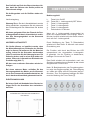
The minimum distance between the cooker
surface and the lower part of the cooker hood
must be 60cm in case of electric cooker and
65 cm in case of gas or mixed kitchens.
If the installation instructions of the appliance for
gas cooking indicate a higher distance, follow the
specic instructions.
Before proceeding with the installation, in order to
avoid damaging the appliance, release the grea-
se lters and the liquid waste tray.
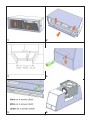
Metal grease lters can be removed by pushing
the lter towards the back side of the hood and
rotating it down, releasing it from its seat (g. 1).
You can release the liquid waste tray by loose-
ning the screws (g.2) and pulling out the metal
tray.
Essential requirements before installing the ap-
pliance are the following ones:
- Realization of a suitable opening on the bot-
tom of the cabinet to proper install the applian-
ce (g. 3).
- Prepare the power supply.
- Prepare an air exhausting hole and the spe-
cic ducting system.
Use an air exhausting duct, whose maximum
length does not exceed 5 m. Limit the number of
bends in the ducting system since every bend re-
duces the suction efciency of 1 linear meter (e.g.
if you use no.2 bends at 90°, the length of the
ducting system must not exceed 3 meters). Use a
150 mm diameter duct for the whole length.
The material of the duct must be compliant with
the regulations in force.
To install the appliance, adjust the position
of the stop side-springs through the proper
screws (g. 4), position the brackets 2-3 mm
over the thickness of the cabinet bottom.
Insert the built-in unit in the hole made in
the cabinet until the stop click of the side-
springs. Use the self-tapping screws 3,9x25
for stopping through the internal holes of the
device (g. 5).
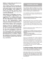
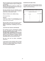
Before making the electrical con-
nections, check that:
-the system ratings meet the ra-
tings indicated on the identica-
tion plate xed on the lower part
of the worktop; -the system is
tted with efcient ground wires
in accordance with the laws and
current standards.
Grounding is mandatory by law.
If the domestic appliance is not
supplied with a cable and/or sui-
table plug, use material suitable
for the absorption value indica-
ted on the identication plate
and the operating temperature. If
wishing to make a direct connec-
tion to the mains, an omnipolar
switch must be installed with a
minimum 3 mm opening betwe-
en the contacts and appropriate
for the load indicated on the pla-
te and in accordance with cur-
rent standards (the yellow/green
ground conductor must not be di-
sconnected by a switch). When
the appliance has been installed,
the omnipolar switch must be ea-
sily reachable.

8
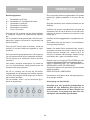
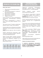
WORKING
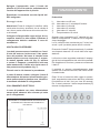
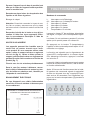
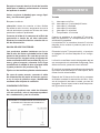
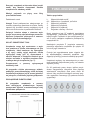
Push button
L: Light switch on/off
0/1: Motor switch on (1st speed)/off
2: Motor switch 2nd speed
3: Motor switch 3rd speed
4: Motor switch 4th speed
T: 10-minutes timer
When the 4th speed of the motor is set, the rela-
ting LED ashes.
After 5 minutes the motor goes back to the 3rd
speed.
By pushing the T button (timer), 10 minutes after
setting it, the range hood is switched off.
The function is highlighted by the led ashing ac-
cording to the set speed. Press again the T but-
ton to disactivate this function.
The product automatically turns off after 4 hours
of uninterrupted working, from the last function
selected.
After 30 hours working, the push button indicates
the saturation of lter by lighting all buttons,for
about 30 seconds.
Press the timer button (T) to reset, while signa-
ling.
Push the appliance towards the bottom of the
cabinet in order to make the frame of the ap-
pliance perfectly adhere to the cabinet.
Restore the liquid waste tray and the grease
lters.
Locking of the valve
Warning!
Before connecting the air outlet exible pipe to
the motor, make sure that the non-return valve,
placed on the air outlet of the motor, is free to
rotate.
Connect the ange of the hood to the exhaust
hole through a suitable duct. Make the electri-
cal connection through the power cable.
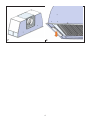
REAR AIR OUTLET
The products can be installed with the air out-
let of the motor towards the back side of the
product. If you want to use this option, you
need to remove the motor support removing
the screws (g. 6), pull out and rotate the sup-
port, position it in its seat keeping the air out-
let towards the rear side of the product (g. 7).
Fix it with the screws previously removed.
In case of external motor, connect the power
cable of the motor to the terminal board in the
black plastic box, identied through the con-
nection label.
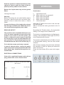
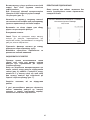
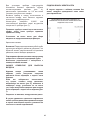
ELECTRICAL CONNECTIONS
If the unit is supplied with power cable with no
plug, please refer to the schema below.
POWER SUPPLY SHOWN IN THE RATING LABEL
3X0.75mm2

An accurate maintenance guarantees a good
functioning and a long-lasting performance.
Pay attention to the grease lters.
The lter can be removed by pushing it towards
the back part of the hood and rotating the lter
downwards, releasing it from its seat (g. 1). To
insert the lter, just perform the opposite opera-
tion.
The grease lter can be washed by hand or in the
dishwasher.
After releasing the steel lters, hold the liquid wa-
ste tray in one hand and, with the other hand, lo-
osen the knobs as indicated in g. 2, let the liquid
waste tray swipe down taking care not to pour
any liquids.
For cleaning, use ONLY a damp cloth with neutral
liquid detergents.
DO NOT USE TOOLS OR INSTRUMENTS FOR
CLEANING!
Avoid using abrasive products.
DO NOT USE ALCOHOL.
The replacement of the power cable must be car-
ried out by authorized staff.
Replacement of the LED bar:
By using an appropriate tool, remove the LED
bar from its seat (Fig. 8), disconnect it elec-
tronically through the appropriate connec-
tor, then replace it with a LED bar having the
same features.
MAINTENANCE
9

INDICE
Avvertenze
Installazione
Funzionamento
Manutenzione
IT
10

di esperienza e conoscenza se
sono posti a supervisione.
I bambini non devono giocare
con l’apparecchio.
La pulizia e la manutenzione non
devono essere eseguite da bam-
bini senza supervisione.
Se il cavo di alimentazione è
danneggiato, esso deve essere
sostituito da un cavo o da un as-
semblaggio speciale, disponibili
presso il costruttore o il suo ser-
vizio assistenza tecnica.
Il locale deve disporre di adegua-
ta ventilazione quando si utilizza
la cappa da cucina contempora-
neamente con altri apparecchi
che impiegano gas o altri com-
bustibili (non si applica agli appa-
recchi che si limitano a scaricare
nuovamente l’aria nel locale);
Esiste la possibilità di incendio
qualora le operazioni di pulizia
non vengano effettuate secondo
quanto indicato nelle istruzioni;
Non preparare alimenti ambé
sotto la cappa da cucina.
ATTENZIONE: Le parti accessi-
bili possono scottare se utilizzate
in concomitanza con gli apparec-
chi di cottura.
Quando la cappa e gli apparec-
chi alimentati con energia diver-
sa dall’elettricità sono in funzione
contemporaneamente, la depres-
sione nell’ambiente non deve su-
perare i 4 Pa (4 x 10⁻⁵ bar).
AVVERTENZE
L’uscita aria dell’apparecchio non
deve essere collegata a un con-
dotto usato per lo scarico di altri
fumi quali impianti di riscalda-
mento, scaldabagni, ecc..
Per l’emissione all’esterno
dell’aria, rispettare le norme vi-
genti.
L’alimentazione dell’eventuale
motore remoto, in caso di prodot-
to privo di motore a bordo, avvie-
ne tramite la cappa posta in cu-
cina.
Prima del collegamento elettrico,
assicurarsi che i valori di tensio-
ne dell’abitazione corrispondano
con quelli delle targhette dati elet-
trici dell’apparecchio.
Prima di procedere a qualsia-
si tipo di operazione di pulizia o
manutenzione, assicurarsi che
l’apparecchio sia scollegato dalla
rete elettrica.
Una buona manutenzione garan-
tisce un buon funzionamento e
un buon rendimento nel tempo.
Tutti i modelli sono in classe I,
pertanto necessitano di collega-
mento a terra.
- Questo apparecchio può essere
utilizzato da bambini di età pari o
superiore a 8 anni e da persone
con ridotte capacità siche, sen-
soriali o mentali o mancanza
11

12
INSTALLAZIONE
La distanza minima fra la supercie di supporto
dei recipienti sul dispositivo di cottura e la par-
te più bassa della cappa da cucina deve essere
non inferiore a 60cm in caso di cucine elettriche
e di 65cm in caso di cucine a gas o miste.
Se le istruzioni di installazione del dispositivo di
cottura a gas specicano una distanza maggiore,
bisogna tenerne conto.
Prima di procedere all’installazione, per evitare
danni dell’apparecchio, disinserire i ltri antigrasso
e la vaschetta raccolta liquidi.
La rimozione dei ltri metallici antigrasso av- viene
spingendo il ltro verso la parte poste- riore della
cappa e facendolo ruotare verso il basso sgan-
ciandolo dalla sua sede (dis.1). La rimozione della
vaschetta raccolta liquidi avviene allentanto le viti
(dis. 2) ed estraendo la vaschetta metallica.
I requisiti essenziali prima di effettuare il montag-
gio dell’apparecchio sono:
- Aver praticato l’apertura necessaria sul fon-
do del pensile giusta ad accogliere l’apparec-
chio (dis. 3 ).
- Predisporre l’alimentazione elettrica.
- Predisporre il foro evacuazione aria e la rela-
tiva canalizzazione.
Utilizzare un tubo di evacuazione aria che abbia
la lunghezza massima non superiore a 5 metri.
Limitare il numero di curve nella canalizzazione
poiché ogni curva riduce l’efcienza di aspirazione
equiparata a 1 metro lineare. (Es: se si utilizza-
no n° 2 curve a 90° la lunghezza della canalizza-
zione non deve superare i 3 metri). Utilizzare un
condotto con diametro 150mm costante per tutta
la lunghezza. Utilizzare un condotto di materiale
approvato normativamente.
Per istallare l’apparecchio, regolare la posizio-
ne delle molle laterali di aggancio tramite le ap-
posite viti (dis. 4), posizionare le staffe 2-3mm
sopra lo spessore del fondo del pensile.
Inserire il gruppo nella sede praticata nel pen-
sile no al completo bloccaggio delle molle
laterali. Utilizzare viti autolettanti 3,9X25 per
il denitivo bloccaggio tramite i fori interni
dell’apparecchio (dis. 5).
Prima di effettuare le connessioni
elettriche assicurarsi che:
- le caratteristiche dell’impianto
siano tali da soddisfare le indica-
zioni sulla targhetta identicativa
applicata sulla parte inferiore del
piano di lavoro;
- l’impianto sia dotato di una mes-
sa a terra efciente conforme alle
norme e alle disposizioni di legge
in vigore.
La messa a terra è obbligatoria
per legge.
Nel caso in cui l’elettrodomestico
non sia dotato di cavo e/o della
relativa spina, utilizzare materiale
adatto per l’assorbimento indicato
nella targhetta identicativa e per
la temperatura di funzionamento.
Se si desidera una connessione
diretta alla linea elettrica, è ne-
cessario interporre un interrutto-
re omnipolare, con un’apertura
minima di 3 mm fra i contatti, ap-
propriato al carico indicato nella
targhetta e conforme alle norme
vigenti (il conduttore di terra gial-
lo/verde non deve essere interrot-
to dal commutatore).
Terminata l’installazione dell’ap-
parecchiatura, l’interruttore om-
nipolare deve essere facilmente
raggiungibile.

13
FUNZIONAMENTO
Pulsantiera
L: Interruttore on/off luce
0/1: Interruttore on (I velocità)/off motore
2: Interruttore II velocità
3: Interruttore III velocità
4: Interruttore IV velocità
T: Temporizzatore 10 minuti
Quando viene impostata la IVa velocità del ven-
tilatore di aspirazione, il relativo LED di segnala-
zione lampeggia.
La IVa velocità viene mantenuta per 5 minuti tra-
scorsi i quali il prodotto passa alla IIIa velocità.
Premendo il tasto T (temporizzazione), il prodotto
verrà spento trascorsi 10 minuti dalla sua impo-
stazione.
La funzione viene segnalata mediante il lampeg-
gio del led corrispondente alla velocità impostata.
Per disattivare la funzione, premere nuovamente
il tasto T.
Il prodotto si spegne automaticamente dopo
quattro ore di lavoro initerrotto, dall’ultima funzio-
ne selezionata.
Dopo 30 ore di esercizio della cappa la pulsan-
tiera, segnalerà la saturazione del ltro, mediante
l’illuminazione di tutti i led, per circa 30 secondi.
Per il reset, premere il tasto temporizzatore (T)
durante la segnalazione
Spingere l’apparecchio verso il fondo del
pensile al ne di far aderire perfettamente la
cornice dell’apparecchio al pensile.
Ripristinare la vaschetta raccolta liquidi ed i
ltri antigrasso.
Bloccaggio valvola
Attenzione! Prima di collegare il tubo es- sibile
uscita aria al motore, accertarsi che la valvola di
non ritorno posta sulla bocca del motore sia libe-
ra di roteare.
Collegare la angia della cappa al foro di eva-
cuazione tramite un tubo adatto. Effettuare il
collegamento elettrico mediante il cavo ali-
mentazione.
USCITA ARIA POSTERIORE
I prodotti possono essere installati con l’usci-
ta aria del motore rivolta verso il lato poste-
riore del prodotto. Nel caso si intenda usare
questa opzione occorre rimuovere il suppor-
to motore agendo sulle viti (g. 6), estrarre
e ruotare il supporto, posizionarlo nella sua
sede mantenendo l’uscita aria rivolta verso il
lato posteriore del prodotto (g. 7).
Fissarlo con le viti rimosse in precedenza.
In caso di motore remoto, collegare il cavo di
alimentazione del motore alla morsettiera pre-
sente nella scatola in plastica nera, identica-
ta mediante etichetta di collegamento.
COLLEGAMENTO ELETTRICO
In caso di prodotto con cavo alimentazione
senza spina, attenersi allo schema qui sotto
per il collegamento.
TENSIONE DI ALIMENTAZIONE RIPORTATA NEL-
LA TARGA DATI TECNICI DEL PRODOTTO
3X0.75mm2

Un’accurata manutenzione garantisce un buon
funzionamento ed un buon rendimento nel tem-
po.
Una cura particolare va rivolta ai ltri antigrasso.
La rimozione del ltro avviene spingendolo verso
la parte posteriore della cappa e facen- do ruo-
tare il ltro verso il basso sganciandolo dalla sua
sede (dis. 1). Il ltro viene inserito nell’operazione
inversa.
La pulizia del ltro antigrasso può essere esegui-
ta a mano o in lavastoviglie.
Dopo aver rimosso i ltri in acciaio, con una mano
sorreggere la vaschetta raccolta liquidi e con l’al-
tra allentare i pomelli come indicato in g. 2, far
scorrere quindi la vaschetta verso il basso facen-
do attenzione a non versare eventuali liquidi.
Per la pulizia usare ESCLUSIVAMENTE un pan-
no inumidito con detersivi liquidi neutri.
NON UTILIZZARE UTENSILI O STRUMENTI
PER LA PULIZIA!
Evitare l’uso di prodotti contenenti abrasivi.
NON UTILIZZARE ALCOOL
La sostituzione del cavo alimentazione deve es-
sere eseguita esclusivamente da personale au-
torizzato.
Sostituzione della barra LED:
Utilizzando un utensile appropriato, rimuo-
vere la barra led dalla sua sede (vedi gura 8)
scollegarla elettronicamente mediante l’appo-
sito connettore quindi sostituirla con una di
pari caratteristiche.
MANUTENZIONE
14

TABLE DES MATIÈRES
Consignes de sécurité
Installation
Fonctionnement
Entretien
FR
15

manquant d’expérience et de con-
naissances si elles sont surveil-
lées.
Les enfants ne doivent pas jouer
avec l’appareil.
Le nettoyage et l’entretien ne doi-
vent pas être effectués par des
enfants sans surveillance.
Si le câble d’alimentation est en-
dommagé, il doit être remplacé
par un câble ou un assemblage
spécial, disponible auprès du fa-
bricant ou de son service d’assi-
stance technique.
La pièce doit disposer d’une ven-
tilation adéquate lorsque la hotte
est utilisée en même temps que
d’autres appareils fonctionnant au
gaz ou à tout autre combustible
(cela ne s’applique pas aux appa-
reils qui rejettent simplement l’air
dans la pièce) ;
Il existe un risque d’incendie si les
opérations de nettoyage ne sont
pas effectuées comme indiqué
dans les instructions.
Ne préparez pas d’aliments am-
bés sous la hotte aspirante.
ATTENTION : Les pièces acces-
sibles peuvent être très chaudes
si elles sont utilisées avec des ap-
pareils de cuisson.
Lorsque la hotte et les appareils
alimentés avec une énergie au-
tre que l’électricité fonctionnent
en même temps, la dépression
dans l’environnement ne doit pas
dépasser 4 Pa (4 x 10⁻⁵ bar).
CONSIGNES DE SÉCURITÉ
La sortie d’air de l’appareil ne doit
pas être raccordée à un conduit
utilisé pour l’évacuation d’autres
fumées telles que les systèmes
de chauffage, les chauffe-eau,
etc.
Pour l’évacuation vers l’extérieur
de l’air, se conformer à la régle-
mentation en vigueur.
L’alimentation électrique d’un mo-
teur à distance, dans le cas d’un
produit sans moteur à bord, s’ef-
fectue via la hotte située dans la
cuisine.
Avant d’effectuer le raccordement
électrique, assurez-vous que les
données de tension de l’habita-
tion correspondent à celles des
plaques de données électriques
de l’appareil.
Avant de procéder à tout type
d’opération de nettoyage ou d’en-
tretien, assurez-vous que l’appa-
reil est débranché du secteur.
Un bon entretien assure un bon
fonctionnement et de bonnes
performances dans le temps.
Tous les modèles sont en classe
I, ils nécessitent donc une conne-
xion à la terre.
- Cet appareil peut être utilisé par
des enfants âgés de 8 ans et plus
et par des personnes ayant des
capacités physiques, sensoriel-
les ou mentales réduites ou 16

17
INSTALLATION
La distance minimale entre la surface d’appui
des récipients sur l’appareil de cuisson et la
partie la plus basse de la hotte ne doit pas être
inférieure à 60 cm pour les cuisinières électri-
ques et à 65 cm pour les cuisinières à gaz ou
mixtes.
Si les instructions d’installation de la plaque de cuis-
son à gaz spécient une distance plus grande, cela
doit être pris en compte.
Avant de procéder à l’installation, an d’éviter d’en-
dommager l’appareil, retirez les ltres à graisse et
le bac de récupération des liquides.
Les ltres à graisse métalliques se retirent en pous-
sant le ltre vers l’arrière de la hotte et en le faisant
pivoter vers le bas, en le dégageant de son siège
(g.1). Le bac de récupération des liquides s’enlève
en desserrant les vis (dis. 2) et en extrayant le bac
métallique.
Avant le montage de l’appareil, les points suivants
sont à effectuer :
- Faire un trou sur le bas du meuble haut néces-
saire à loger l’appareil (dess. 3).
- Préparer l’alimentation.
- Préparer le trou d’évacuation de l’air ainsi que
les conduits.
Utilisez un tuyau d’évacuation d’air d’une longueur
maximale ne dépassant pas 5 mètres. Limitez le
nombre de coudes dans le conduit puisque chaque
coude réduit l’efcacité d’aspiration équivalente à 1
mètre linéaire. (Ex : si 2 coudes à 90° sont utilisés,
la longueur de la canalisation ne doit pas dépas-
ser 3 mètres). Utilisez un conduit d’un diamètre
constant de 150 mm sur toute la longueur. Utilisez
un conduit fait d’un matériau approuvé par la régle-
mentation.
Pour installer l’appareil, réglez la position des
ressorts d’accrochage latéraux à l’aide des vis
(dess. 4), positionnez les étriers à 2-3 mm au-
dessus de l’épaisseur du bas du meuble haut.
Insérez le groupe dans le logement réalisé dans
le meuble haut jusqu’au blocage complet des
ressorts latéraux. Utilisez des vis autotaraudeu-
ses 3,9X25 pour un blocage dénitif à travers
les trous internes de l’appareil (g. 5).
Avant d’effectuer les raccorde-
ments électriques, assurez-vous
que :
- Les caractéristiques de l’instal-
lation correspondent aux don-
nées indiquées sur la plaque si-
gnalétique apposée au dessous
du plan de travail.
- L’installation est équipée d’une
mise à la terre adéquate confor-
me aux normes et dispositions de
loi en vigueur.
La mise à la terre est requise par
la loi.
Si l’appareil n’est pas équipé d’un
câble et/ou de sa che, utiliser un
matériau adapté à l’absorption in-
diquée sur la plaque signalétique
et à la température de fonction-
nement. Si une connexion directe
à la ligne électrique est requise,
il faut interposer un interrupteur
omnipolaire ayant une ouvertu-
re minimale de 3 mm entre les
contacts, adapté à la charge in-
diquée sur la plaque et conforme
à la réglementation en vigueur (le
conducteur de terre jaune/vert ne
doit pas être interrompue par le
commutateur).
Une fois l’appareil installé, l’inter-
rupteur omnipolaire doit être faci-
lement accessible.

18
FONCTIONNEMENT
Bandeau de commande
L: Interrupteur on/off éclairage
0/1: Interrupteur on (I vitesse)/off moteur
2: Interrupteur II vitesse
3: Interrupteur III vitesse
4: Interrupteur IV vitesse
T: Temporisateur 10 minutes
Lorsque la vitesse IVa du ventilateur d’aspiration
est réglée, le voyant- LED correspondant cligno-
te.
La vitesse IVa est maintenue pendant 5 minutes
après quoi le produit passe à la vitesse IIIa.
En appuyant sur la touche T (temporisateur),
l’appareil s’éteint automatiquement après 10 mi-
nutes dès son réglage.
La fonction est signalée par le clignotement du
voyant-LED correspondant à la vitesse réglée.
Pour désactiver la fonction, appuyez à nouveau
sur la touche T.
Le produit s’éteint automatiquement après quatre
heures de fonctionnement continu, dès la derniè-
re fonction sélectionnée.
Après 30 heures de fonctionnement de la hotte,
le bandeau de commande signale la saturation
du ltre en allumant tous les voyants-LED pen-
dant environ 30 secondes. Pour réinitialiser, ap-
puyez sur la touche temporisateur (T) pendant la
signalisation.
Pousser l’appareil vers le bas du meuble haut
an que le cadre de l’appareil adhère parfaite-
ment au meuble haut.
Remettez en place le bac de récupération des
liquides et les ltres à graisse.
Blocage du clapet
Attention ! Avant de raccorder le tuyau de sor-
tie d’air au moteur, assurez-vous que le clapet
anti-retour situé à l’entrée du moteur est libre de
tourner.
Raccordez la bride de la hotte au trou d’éva-
cuation à l’aide d’un tuyau approprié. Effec-
tuez le raccordement électrique à l’aide du
câble d’alimentation.
SORTIE D’AIR ARRIÈRE
Les appareils peuvent être installés avec la
sortie d’air du moteur tournée vers l’arriè-
re du produit. Si vous comptez utiliser cette
option, retirez le support moteur en agissant
sur les vis (g. 6), retirez et faites pivoter le
support, positionnez-le dans son logement en
gardant la sortie d’air tournée vers l’arrière du
produit (g. 7).
Fixez-le avec les vis enlevées précédemment.
Dans le cas d’un moteur à distance, raccor-
dez le câble d’alimentation du moteur au bor-
nier du boîtier en plastique noir, identié par
l’étiquette de raccordement.
BRANCHEMENT ÉLECTRIQUE
En cas d’appareil avec câble d’alimentation
sans che, suivez le schéma ci-dessous pour
le raccordement.
TENSIONE DI ALIMENTAZIONE RIPORTATA NEL-
LA TARGA DATI TECNICI DEL PRODOTTO
3X0.75mm2

Un entretien soigné assure un bon fonctionne-
ment et de bonnes performances dans le temps.
Une attention particulière doit être portée aux l-
tres à graisse.
Pour retirer le ltre poussez-le vers l’arrière de
la hotte et puis pivotez-le vers le bas en le déga-
geant de son siège (dess.. 1). Replacez le ltre
dans l’opération inverse.
Le ltre à graisse peut être nettoyé à la main ou
au lave-vaisselle.
Après avoir retiré les ltres en acier, d’une main
tenez le bac de récupération des liquides et de
l’autre desserrez les pommeaux comme indiqué
à la g. 2, puis faites glisser le bac vers le bas en
veillant à ne pas renverser de liquide.
Pour le nettoyage, utilisez UNIQUEMENT un
chiffon imbibé de détergents liquides neutres.
N’UTILISEZ PAS D’OUTILS OU D’INSTRU-
MENTS POUR LE NETTOYAGE !
Évitez d’utiliser des produits contenant des abra-
sifs. NE PAS UTILISER D’ALCOOL
Le remplacement du câble d’alimentation ne doit
être effectué que par du personnel autorisé.
Remplacement de la barre à LED :
A l’aide d’un outil approprié, retirez la barre à
LED de son logement (voir gure 8), décon-
nectez-la électroniquement par le connecteur
puis remplacez-la par une aux mêmes carac-
téristiques.
ENTRETIEN
19

ÍNDICE
Advertencias
Instalación
Funcionamiento
Mantenimiento
ES
20
Strona się ładuje...
Strona się ładuje...
Strona się ładuje...
Strona się ładuje...
Strona się ładuje...
Strona się ładuje...
Strona się ładuje...
Strona się ładuje...
Strona się ładuje...
Strona się ładuje...
Strona się ładuje...
Strona się ładuje...
Strona się ładuje...
Strona się ładuje...
Strona się ładuje...
Strona się ładuje...
Strona się ładuje...
Strona się ładuje...
Strona się ładuje...
Strona się ładuje...
Strona się ładuje...
Strona się ładuje...
Strona się ładuje...
Strona się ładuje...
Strona się ładuje...
Strona się ładuje...
Strona się ładuje...
Strona się ładuje...
Strona się ładuje...
Strona się ładuje...
Strona się ładuje...
Strona się ładuje...
-
 1
1
-
 2
2
-
 3
3
-
 4
4
-
 5
5
-
 6
6
-
 7
7
-
 8
8
-
 9
9
-
 10
10
-
 11
11
-
 12
12
-
 13
13
-
 14
14
-
 15
15
-
 16
16
-
 17
17
-
 18
18
-
 19
19
-
 20
20
-
 21
21
-
 22
22
-
 23
23
-
 24
24
-
 25
25
-
 26
26
-
 27
27
-
 28
28
-
 29
29
-
 30
30
-
 31
31
-
 32
32
-
 33
33
-
 34
34
-
 35
35
-
 36
36
-
 37
37
-
 38
38
-
 39
39
-
 40
40
-
 41
41
-
 42
42
-
 43
43
-
 44
44
-
 45
45
-
 46
46
-
 47
47
-
 48
48
-
 49
49
-
 50
50
-
 51
51
-
 52
52


ELICA PRF0183203 Built In Hood Cm 60 Instrukcja obsługi
- Typ
- Instrukcja obsługi
w innych językach
- español: ELICA PRF0183203 Built In Hood Cm 60 Instrucciones de operación
- italiano: ELICA PRF0183203 Built In Hood Cm 60 Istruzioni per l'uso
- Deutsch: ELICA PRF0183203 Built In Hood Cm 60 Bedienungsanleitung
- français: ELICA PRF0183203 Built In Hood Cm 60 Mode d'emploi
- Nederlands: ELICA PRF0183203 Built In Hood Cm 60 Handleiding