
POWER SUPPLY
Owner’s Manual
Mode d’emploi
Bedienungsanleitung
M

2
FCC INFORMATION (U.S.A.)
1. IMPORTANT NOTICE: DO NOT MODIFY THIS UNIT! This product, when installed as indicated in the instructions contained in this manual, meets FCC
requirements. Modifications not expressly approved by Yamaha may void your authority, granted by the FCC, to use the product.
2. IMPORTANT: When connecting this product to accessories and/or another product use only high quality shielded cables. Cable/s supplied with this product MUST
be used. Follow all installation instructions. Failure to follow instructions could void your FCC authorization to use this product in the USA.
3. NOTE: This product has been tested and found to comply with the requirements listed in FCC Regulations, Part 15 for Class “B” digital devices. Compliance with
these requirements provides a reasonable level of assurance that your use of this product in a residential environment will not result in harmful interference with
other electronic devices. This equipment generates/uses radio frequencies and, if not installed and used according to the instructions found in the users manual, may
cause interference harmful to the operation of other electronic devices. Compliance with FCC regulations does not guarantee that interference will not occur in all
installations. If this product is found to be the source of interference, which can be determined by turning the unit “OFF” and “ON”, please try to eliminate the
problem by using one of the following measures: Relocate either this product or the device that is being affected by the interference. Utilize power outlets that are on
different branch (circuit breaker or fuse) circuits or install AC line filter/s. In the case of radio or TV interference, relocate/reorient the antenna. If the antenna lead-in
is 300 ohm ribbon lead, change the lead-in to coaxial type cable. If these corrective measures do not produce satisfactory results, please contact the local retailer
authorized to distribute this type of product. If you can not locate the appropriate retailer, please contact Yamaha Corporation of America, Electronic Service
Division, 6600 Orangethorpe Ave, Buena Park, CA 90620
The above statements apply ONLY to those products distributed by Yamaha Corporation of America or its subsidiaries.
WARNING: THIS APPARATUS MUST BE EARTHED
IMPORTANT
THE WIRES IN THIS MAINS LEAD ARE COLOURED IN
ACCORDANCE WITH THE FOLLOWING CODE:
GREEN-AND-YELLOW : EARTH
BLUE : NEUTRAL
BROWN : LIVE
As the colours of the wires in the mains lead of this apparatus may
not correspond with the coloured markings identifying the terminals in
your plug, proceed as follows:
The wire which is coloured GREEN and YELLOW must be
connected to the terminal in the plug which is marked by the letter E
or by the safety earth symbol or coloured GREEN and YELLOW.
The wire which is coloured BLUE must be connected to the terminal
which is marked with the letter N or coloured BLACK.
The wire which is coloured BROWN must be connected to the
terminal which is marked with the letter L or coloured RED.
* This applies only to products distributed by YAMAHA KEMBLE
MUSIC (U.K.) LTD.

3
■
Precautions
• Connect the power supply power cord only to an AC
outlet of the type stated in this
Owner’s Manual
or as
marked on the power supply unit. Failure to do so is a
fire and electrical shock hazard.
• Do not locate the power supply unit in a place subject
to excessive heat or in direct sunlight. This could be a
fire hazard.
• Do not place the power supply unit in a place subject
to excessive humidity or dust. This could be a fire and
electrical shock hazard.
• Do not plug several devices into the same AC outlet.
This may overload the AC outlet, and could be a fire
and electrical shock hazard. It may also affect the per-
formance of some equipment.
• Do not place heavy objects on the power cord. A dam-
aged power cord is a potential fire and electrical shock
hazard.
• If the power cord is damaged (i.e., cut or a bare wire is
exposed), ask your dealer for a replacement. Using the
power supply unit in this condition is a fire and shock
hazard.
• Hold the power cord plug when disconnecting from
an AC outlet. Never pull the cord. Damaging the
power cord in this way is a potential fire and electrical
shock hazard.
• Do not place small metal objects on top of the power
supply unit. Metal objects inside the power supply
unit are a fire and electrical shock hazard.
• Do not block the power supply unit ventilation slots.
The power supply unit has ventilation slots at the
front to prevent the internal temperature from rising.
Blocked ventilation slots are a fire hazard.
• Leave a reasonable amount of free-air space around
the power supply unit.
• If the power supply unit is to be rack mounted, leave
at least 10 cm free above the top panel and behind the
rear panel. When the power supply unit is in use,
remove the rear of the rack, or open its ventilation
slots to prevent overheating, which could be a fire
hazard.
• Do not try to modify the power supply unit. This
could be a fire and electrical shock hazard.
• The power supply unit operating temperature is
between 5˚C and 35˚C (41˚F and 95˚F).
• Turn off all audio devices and speakers when connect-
ing to the power supply unit. Refer to the owner’s
manual for each device. Use the correct cables and
connect as specified.
• If you notice any abnormality—such as smoke, odor,
or noise—turn off the power supply unit immediately.
Remove the power cord from the AC outlet. Confirm
that the abnormality is no longer present. Consult
your dealer for repair. Using the power supply unit in
this condition is a fire and shock hazard.
• If a foreign object or water gets inside the power sup-
ply unit, turn it off immediately. Remove the power
cord from the AC outlet. Consult your dealer for
repair. Using the power supply unit in this condition
is a fire and electrical shock hazard.
• If you plan not to use the power supply unit for a long
period of time, remove the power cord from the AC
outlet. Leaving the power supply unit connected is a
fire hazard.
• Do not use benzene, thinner, cleaning detergent, or a
chemical cloth to clean the power supply unit. Use
only a soft, dry cloth.
• The power supply unit uses high-frequency digital cir-
cuits that may cause interference on radios and televi-
sions placed close to it. If interference does occur,
relocate the affected equipment.

4
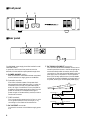
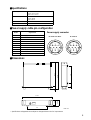
■
Front panel
■
Rear panel
The PW3000M power supply should be installed in a well
ventilated location.
In particular, the front and rear panels must not be
blocked, since the ventilation path passes through them.
A
POWER ON/OFF
switch
After connections to the M3000 have been completed,
turn this switch on to supply power to the M3000.
B
Operation monitor
Four LEDs indicate the status of the power that is
being supplied to the M3000. Normally (i.e., when no
malfunction has occurred), the green LEDs (NOR-
MAL) will light. If a malfunction occurs, the LED for
that section of the power supply will go dark. Turn the
power off and wait for a time before turning the
power on again. If the same LED(s) are dark, contact a
Yamaha service center.
C
GND terminals
This is the grounding screw terminal. If hum or noise
occurs, ground (earth) the unit via this jack, or try
connecting it to the chassis of the other device.
D
DC OUTPUT
connector
Connect this connector to the M3000 to supply power
to it.
E
DC PARALLEL INPUT
connector
This connector allows two PW3000M units to be con-
nected in parallel. As shown in the following diagram,
use the included parallel connection cable to make
connections. In this case, the two PW3000M units will
each supply 50% of the power in normal operation.
Even in the unlikely event that one of the PW3000M
units failed, the other PW3000M will supply 100% of
the power, ensuring an uninterrupted power supply.
POWER
OPERATION MONITOR
POWER SUPPLY
ON/ OFF
NORMAL
+48V +12V +15V –15V
1 2
DC OUTPUT
CONNECT
DISCONNECT
PIN 2 +15V 4.2A
PIN 5 –15V 4.2A
PIN 6 +12V 4.1A
PIN 9 +48V 0.2A
DC PARALLEL INPUT
CONNECT
DISCONNECT
5 4
3
DC OUTPUT
CONNECT
DISCONNECT
PIN 2 +15V 4.2A
PIN 5 –15V 4.2A
PIN 6 +12V 4.1A
PIN 9 +48V 0.2A
DC PARALLEL INPUT
CONNECT
DISCONNECT
DC OUTPUT
CONNECT
DISCONNECT
PIN 2 +15V 4.2A
PIN 5 –15V 4.2A
PIN 6 +12V 4.1A
PIN 9 +48V 0.2A
DC PARALLEL INPUT
CONNECT
DISCONNECT
M3000
PW3000M
PW3000M
DC POWER
INPUT
DC OUTPUT
DC OUTPUT
DC PARALLEL
INPUT

5
■
Specifications
■
Power supply cable pin configuration
■
Dimensions
• Specifications and appearance are subject to change without notice for improvement.
Power Requirements USA and Canada: 120 V, 60 Hz
Europe: 230 V, 50 Hz
Others: 240 V, 50 Hz
Power Consumptions USA and Canada: 400 W, 540 VA
Europe: 380 W
Others: 380 W
Dimension (W x H x D) 480mm x 103.5mm x 455mm
Weight 15kg
Pin No. Signal name
Power supply connector
1 Power supply remote
2 +15 V
3
±
15 V GND
4 +48 V GND
5 –15 V
6 +12 V
7 +12V GND/ power supply remote
8 Power supply remote
9 +48 V
10 FRAME GND
DC OUTPUT
DC PARALLEL INPUT
123
8910
5467
321
1098
6754
D:455
W:480
88
H:103.5
56.8 292
308
49.4 405.6
Units: mm
-
 1
1
-
 2
2
-
 3
3
-
 4
4
-
 5
5


w innych językach
- čeština: Yamaha PW3000M Uživatelský manuál
- español: Yamaha PW3000M Manual de usuario
- italiano: Yamaha PW3000M Manuale utente
- Deutsch: Yamaha PW3000M Benutzerhandbuch
- svenska: Yamaha PW3000M Användarmanual
- português: Yamaha PW3000M Manual do usuário
- français: Yamaha PW3000M Manuel utilisateur
- 日本語: Yamaha PW3000M ユーザーマニュアル
- Türkçe: Yamaha PW3000M Kullanım kılavuzu
- English: Yamaha PW3000M User manual
- dansk: Yamaha PW3000M Brugermanual
- русский: Yamaha PW3000M Руководство пользователя
- Nederlands: Yamaha PW3000M Handleiding
- română: Yamaha PW3000M Manual de utilizare