Nexo NX242 Instrukcja obsługi
- Kategoria
- Wzmacniacze dźwięku
- Typ
- Instrukcja obsługi


ENGLISH
PAGE 2
IMPORTANT SAFETY INSTRUCTIONS
NX242 USER MANUAL LOAD2_22
DATE : 12/9/2004
Declaration of conformity
This equipment has been tested and found to comply with the safety objectives and essential requirements of European (73/23/EEC and
89/336/EEC directives) and international Standards, by fulfilling the requirements of the following harmonized standards:
Electrical Safety (EU) : IEC 60065 (12/2001) Audio, video and similar electronic apparatus
Electrical Safety (US) : UL60065 Seventh Edition, dated June 30, 2003 category AZSQ, E241312.
Electrical Safety (CAN) : CSA-C22.2 N°60065:03 Edition, dated April 2003 category AZSQ7, E241312
Electrical Safety (Rest of the World) : CB test certificate DK-8371 based on IEC60065-2001 7nd ed. with all national deviations.
Radiated Emission (EU) : EN55103-1 (1996) Electromagnetic compatibility - Product family standard for audio, video, audio-
visual and entertainment lighting control apparatus for professional use.
Radiated Emission (US) : FFC part15 class B
Radiated Emission (CAN) : This Class B digital apparatus complies with Canadian ICES-003.
RF Immunity (EU) : EN55103-2 (1996) Electromagnetic compatibility - Product family standard for audio, video, audio-visual and
entertainment lighting control apparatus for professional use.
Note: EMC conformance testing is based on the use of recommended cable types. The use of other cable types may degrade EMC
performances.
IMPORTANT SAFETY INSTRUCTIONS
1) Read these instructions.
2) Keep these instructions.
3) Heed all warnings.
4) Follow all instructions.
5) Do not use this apparatus near water.
6) Clean only with dry cloth.
7) Do not block any ventilation openings. Install in accordance with the
manufacturer’s instructions.
8) Do not install near any heat sources such as radiators, heat registers,
stoves, or other apparatus (including amplifiers) that produce heat.
9) Do not defeat the safety purpose of the polarized or grounding-type plug. A
polarized plug has two blades with one wider than the other. A grounding type
plug has two blades and a third grounding prong. The wide blade or the third
prong are provided for your safety. If the provided plug does not fit into your
outlet, consult an electrician for replacement of the obsolete outlet. (US
market)
10) Protect the power cord from being walked on or pinched particularly at
plugs, convenience receptacles, and the point where they exit from the
apparatus.
11) Only use attachments/accessories specified by the manufacturer.
13) Unplug this apparatus during lightning storms or when unused for long
periods of time.
14) Refer all servicing to qualified service personnel. Servicing is required
when the apparatus has been damaged in any way, such as power-supply
cord or plug is damaged, liquid has been spilled or objects have fallen into the
apparatus, the apparatus has been exposed to rain or moisture, does not
operate normally, or has been dropped.
Information about products that generate electrical noise :
NOTE: The United States Federal Communications Commission (in 47 CFR
15.105) has specified that the following notice be brought to the attention of
users of this product:
This equipment has been tested and found to comply with the limits for a
Class B digital device, pursuant to Part 15 of the FCC Rules. These limits are
designed to provide reasonable protection against harmful interference in a
residential installation. This equipment generates, uses and can radiate radio
frequency energy and, if not installed and used in accordance with the
instructions, may cause harmful interference to radio communications.
However, there is no guarantee that interference will not occur in a particular
installation. If this equipment does cause harmful interference to radio or
television reception, which can be determined by turning the equipment off
and on, the user is encouraged to try to correct the interference by one or
more of the following measures:
- Reorient or relocate the receiving antenna.
- Increase the separation between the equipment and receiver.
- Connect the equipment into an outlet on a circuit different from that to which
the receiver is connected.
- Consult the dealer or an experienced radio/TV technician for help.
The user may find the following booklet, prepared by the Federal
Communications Commission, helpful: How to identify and Resolve Radio/TV
Interference Problems. This booklet is available from the U.S. Government
Printing Office, Washington, D.C. 20402, Stock No. 004-000-00345-4. Use of
a shielded cable is required to comply within Class B limits of Part 15 of FCC
Rules. Pursuant to Part 15.21 of the FCC Rules, any changes or
modifications to this equipment not expressly approved by NEXO S.A. may
cause, harmful interference and void the FCC authorization to operate this
equipment.
WARNING ! This appliance is a CLASS 1 apparatus and must be earthed.
The green and yellow wire of the mains cord must always be connected to an installation safety earth or ground. The earth is essential for
personal safety as well as the correct operation of the system, and is internally connected to all exposed metal surfaces. Additional
recommendation for interconnection to other equipment can be found in the “Setting-Up Advice” section page 8.
To avoid electrical shock, do not remove covers.
Dangerous voltages exist inside.
Refer all servicing to qualified personnel only.
WARNING: To reduce the risk of fire or electric shock,
do not expose this apparatus to rain or moisture.
RISK OF ELECTRIC SHOCK
DO NOT OPEN
CAUTION
The lightning flash with arrowhead
symbol, within an equilateral triangle
is intended to alert the user to the
presence of uninsulated “dangerous
voltage” within the product's
enclosure that may be of sufficient
magnitude to constitute a risk of
electric shock to persons.
The exclamation point within an
equilateral triangle is intended to
alert the user to the presence of
important operating and
maintenance (servicing) instructions
in the literature accompanying
the appliance.
10CE
A
udio Equipment
10CE
A
udio Equipment

ENGLISH
PAGE 3
INSTRUCTIONS DE SECURITE IMPORTANTES
USER MANUAL LOAD2_22
DATE: 09/12/2004
Déclaration de conformité
Cet équipement a été testé et répond aux objectifs de sécurité et exigences essentielles de la directive 73/23/EEC sur les basses tensions et la
directive 89/336 EEC sur la compatibilité électromagnétique, notamment:
Sécurité électrique (EU) : IEC 60065 (12/2001) Appareils audio, vidéo et appareils électroniques analogues - Exigences de sécurité
Sécurité électrique (US) : UL60065 Seventh Edition, dated June 30, 2003 category AZSQ, E241312.
Sécurité électrique (CAN) : CSA-C22.2 N°60065:03 Edition, dated April 2003 category AZSQ7, E241312
Sécurité électrique (Reste du Monde) : Certificat OC DK-8371 basé sur IEC60065-2001 7eme ed. Toutes deviations
Emission rayonnée (EU) : EN55103-1 (1996) Compatibilité électromagnétique : Norme de famille de produits pour les appareils a
usage professionnel audio, vidéo, audiovisuels et de commande de lumière pour spectacles Partie 1 : émissions
Emission rayonnée (US) : FFC part15 class B
Emission rayonnée (CAN) : This Class B digital apparatus complies with Canadian ICES-003.
Immunité RF (EU) : EN55103-2 (1996) Compatibilité électromagnétique : Norme de famille de produits pour les appareils a usage
professionnel audio, vidéo, audiovisuels et de commande de lumière pour spectacles: Partie 2 : immunités
Note: Les tests de conformité électromagnétique ont été réalisés avec les câbles recommandés dans ce manuel. L’utilisation des
même câbles est nécessaire afin de rester dans le cadre des réglementations énoncées ci dessus.
INSTRUCTIONS DE SECURITE IMPORTANTES
1) Lisez ces instructions.
2) Gardez ces instructions.
3) Tenez compte de tous les avertissements.
4) Suivez toutes les instructions.
5) N’utilisez pas cet appareil à proximité d’eau.
6) Nettoyez uniquement avec un chiffon sec.
7) Ne bloquez aucune ouverture de ventilation. Installez
conformément aux instructions du fabriquant.
8) N’installez pas à proximité d’une source de chaleur telle que
radiateur, chauffage, poêle, ou autre appareil (y compris
amplificateurs) qui produisent de la chaleur.
9) Ne supprimez pas le dispositif de sécurité de la prise polarisée
ou de terre.
10) Protégez le cordon secteur contre les pincements ou
piétinements en particulier à proximité des prises, des réceptacles
adaptés, et à l’endroit ou il sort de l’appareil
11) N’utilisez que des accessoires ou fixations spécifiées par le
fabriquant
13) Débranchez cet appareil pendant les orages ou lors d’une
longue période sans utilisation.
14) Confiez toute la maintenance à du personnel qualifié .La
maintenance est nécessaire quand l’appareil a été endommagé
d’une manière quelconque, comme le cordon d’alimentation
secteur endommagé, du liquide renversé ou des objets étant
tombés dans l’appareil, l’appareil ayant été exposé à la pluie ou à
l’humidité, ne fonctionne pas normalement, ou est tombé.
AVERTISSEMENT! Cet appareil appartient à la CLASSE 1 et doit être mis à la terre.
Le conducteur vert et jaune du câble secteur doit toujours être connecté à la terre de sécurité d'une installation. La terre est essentielle pour la
sécurité du personnel comme pour le bon fonctionnement du système. Elle est connectée à l'intérieur à toutes les surfaces métalliques
exposées. Des recommandations supplémentaires pour l'interconnection avec d'autres équipements se trouvent dans la section ″ ″ Page 44.
To avoid electrical shock, do not remove covers.
Dangerous voltages exist inside.
Refer all servicing to qualified personnel only.
WARNING: To reduce the risk of fire or electric shock,
do not expose this apparatus to rain or moisture.
RISK OF ELECTRIC SHOCK
DO NOT OPEN
CAUTION
The lightning flash with arrowhead
symbol, within an equilateral triangle
is intended to alert the user to the
presence of uninsulated “dangerous
voltage” within the product's
enclosure that may be of sufficient
magnitude to constitute a risk of
electric shock to persons.
The exclamation point within an
equilateral triangle is intended to
alert the user to the presence of
important operating and
maintenance (servicing) instructions
in the literature accompanying
the appliance.
10CE
A
udio Equipment
10CE
A
udio Equipment

ENGLISH
PAGE 4
INSTRUCTIONS DE SECURITE IMPORTANTES
TABLE OF CONTENT
NX242 VERSUS NX241: WHAT’S NEW ? ........................................................................................................................6
WHAT’S REMAIN THE SAME? ..................................................................................................................................................6
WHAT’S CHANGED?.................................................................................................................................................................6
QUICK START......................................................................................................................................................................7
RESET......................................................................................................................................................................................7
SELECTING CABINET FAMILY.....................................................................................................................................................7
SELECT YOUR CABINET SET-UP..................................................................................................................................................7
NAVIGATING MENUS .................................................................................................................................................................7
BACK TO DEFAULT ....................................................................................................................................................................7
AUTO SAVE ...............................................................................................................................................................................7
SETTING-UP ADVICE.........................................................................................................................................................8
MAINS POWER ..........................................................................................................................................................................8
VOLTAGE SETTING ....................................................................................................................................................................8
MOUNTING THE TDCONTROLLER IN A RACK (GROUNDING, SHIELDING & SAFETY ISSUES) .......................................................8
FUSE .........................................................................................................................................................................................8
RECOMMENDATIONS FOR WIRING THE SENSE LINES ..................................................................................................................9
RECOMMENDATIONS FOR WIRING THE AUDIO OUTPUTS.............................................................................................................9
ELECTROMAGNETIC ENVIRONMENTS ........................................................................................................................................9
ANALOGUE SIGNAL CABLES ......................................................................................................................................................9
GENERAL DESCRIPTION ...............................................................................................................................................12
GLOBAL ARCHITECTURE.......................................................................................................................................................12
SET-UP CONFIGURATIONS......................................................................................................................................................12
BLOCK DIAGRAM DESCRIPTION................................................................................................................................13
EQUALISATION & FILTERING ...............................................................................................................................................13
SUBSONIC AND VHF FILTERING (1).........................................................................................................................................13
EQUALISING WIDEBAND ACOUSTICAL RESPONSE (2)...............................................................................................................13
EQUALISING SINGLE COMPONENT RESPONSE (3) .....................................................................................................................13
CROSSOVER SECTION (4).........................................................................................................................................................13
USER SET-UP, ARRAY EQ (5)....................................................................................................................................................13
PROTECTION..........................................................................................................................................................................15
VCAS (6) AND VCEQS (7)......................................................................................................................................................15
DISPLACEMENT CONTROL (8)..................................................................................................................................................15
TEMPERATURE CONTROL (9)...................................................................................................................................................15
PHYSIOLOGIC DYNAMIC CONTROL (10)..................................................................................................................................15
INTERCHANNEL REGULATION (11) ..........................................................................................................................................16
PEAK LIMITER (12)..................................................................................................................................................................16
DELAY & POLARITY INVERSION (13)....................................................................................................................................16
FACTORY SET-UP DELAY...........................................................................................................................................................16
USER SET-UP DELAY................................................................................................................................................................17
AUDIO INPUT/OUTPUT...........................................................................................................................................................17
FLOATING BALANCED AUDIO INPUT ........................................................................................................................................17
BALANCED AUDIO OUTPUT......................................................................................................................................................17
GENERAL FUNCTIONS............................................................................................................................................................18
REMOTE SENSE LINES..............................................................................................................................................................18
RESET .....................................................................................................................................................................................18
NX242 USER MANUAL LOAD2_22
DATE : 12/3/2004

ENGLISH
PAGE 5
INSTRUCTIONS DE SECURITE IMPORTANTES
MUTE/SOLO BUTTONS.............................................................................................................................................................18
DISPLAY & INDICATORS..........................................................................................................................................................18
CONTRAST ADJUSTMENT .........................................................................................................................................................18
SERIAL LINK / DOWNLOADER ..................................................................................................................................................18
MENU DESCRIPTION.......................................................................................................................................................19
MAIN FAMILY SELECTION ....................................................................................................................................................19
USER SETTINGS ......................................................................................................................................................................19
SYSTEM SETTINGS..................................................................................................................................................................22
CONFIGURATION SELECT. .....................................................................................................................................................23
AMPLIFIERS (GAIN, POWER)........................................................................................................................................25
POWER ...................................................................................................................................................................................25
CURRENT RATING ..................................................................................................................................................................25
AMPLIFIER GAINS ..................................................................................................................................................................25
HOW TO SET CORRECT GAIN AND POWER INFORMATION IN THE NX242 .............................................................................25
GAIN VALUE ...........................................................................................................................................................................28
ADVANCED PROTECTIONS .....................................................................................................................................................28
AMPLIFIER LATENCY EFFECTS ON PROTECTION..................................................................................................................28
INSTALLATION RECOMMENDATIONS......................................................................................................................29
AUDIO CHAIN RECOMMENDATIONS......................................................................................................................................29
ABOUT « LOUDSPEAKER MANAGEMENT DEVICES » ...............................................................................................................29
OPERATING SUB’S FED THROUGH AN AUX OUTPUT ...............................................................................................................29
OPERATION OF MULTIPLE TDCONTROLLERS...........................................................................................................................29
SYSTEM ALIGNMENT..............................................................................................................................................................29
GEOMETRICAL ALIGNMENT .....................................................................................................................................................30
MEASURING AND ALIGNING PHASE IN THE OVERLAPPING REGION ...........................................................................................30
NEXO WINDOWS LOADER.............................................................................................................................................32
WARNING ...............................................................................................................................................................................32
CONNECTION FROM NX242 RS232 9-PIN SERIAL PORT TO PC’S COM PORT...................................................................32
INSTRUCTIONS........................................................................................................................................................................32
TECHNICAL SPECIFICATIONS.....................................................................................................................................34
APPLICATION NOTE : DRIVING THE SUB FROM THE AUX SEND.....................................................................35
WHAT IS THE PHASE RELATION BETWEEN THE AUX AND MAIN OUTPUT OF YOUR DESK?.....................................................35
WHY IT IS UNLIKELY THE AUX AND MAIN HAVE THE SAME PHASE? .....................................................................................35
CONSEQUENCES OF BADLY ALIGNED SYSTEMS........................................................................................................................35
PRECAUTIONS & CHECK ..........................................................................................................................................................36
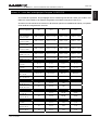
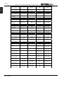
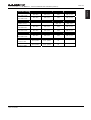
APPENDIX A : LIST OF SUPPORTED PRESETS (LOAD2.22)..................................................................................37
USER MANUAL LOAD2_22
DATE: 03/12/2004

ENGLISH
PAGE 6
NX242 VERSUS NX241: WHAT’S NEW ?
NX242 versus NX241: What’s new ?
The NX242 Digital TDcontroller has been designed in order to provide total compatibility with its
predecessor – the NX241 Digital TDcontroller.
What’s remain the same?
The DSP resources for both models remain the same, so new supported set-ups (i.e. firmware loads) will
be compatible with the both the NX241 and NX242 TDcontrollers. For advanced set-ups and signal
processing NEXO has released the NXtension Expander Board, which has double the available DSP
resources.
MENUs and functions remain the same; no learning curve is needed to go from the NX241 to the NX242.
The same LOAD and NXWIN software is used to update both TDcontrollers. The transition is transparent
for the user. Note however, that the NX242 can’t be flashed with LOADs prior to 2.21.
The appearance of the NX242 is identical to the NX241 except the model number. Therefore, you can
mix both units in the same rack without aesthetic problems. Please note however that both NX241 and
NX242 should have the same firmware revision (LOAD) to be phase compatible.
What’s changed?
The overall performance of the NX242 has improved significantly: 10dB more on the dynamic range, less
distortion…
The layout and ground scheme of the unit have been totally revised to cope with the most demanding
situations founded in the field (low and very high frequencies). The EMC protection on every input/output
and the new ground structure makes the NX242 immune to interference far beyond the recommended
values founded in EMC standards. As a result, there is no need for the earth lift function found on the
NX241.
The input stage is truly floating and accepts important common mode offset (resulting from very long
wiring or difference of ground potential between two connected equipments) without affecting it’s
headroom (28dBu) and performance.
The NX242 Digital TDcontroller uses a switch mode power supply (SMPS). This SMPS accepts
universal AC power input voltages in the range 90V to 264V, and requires no manual adjustment for
voltages in this range.
The NX242 is designed to accept the optional NXtension board with the ES-4 EtherSound interface and
the CAI interface, whereas the NX241 can only accept the CAI interface.
An external LCD contrast adjustment is now provided on the NX242.
NX242 USER MANUAL LOAD2_22
DATE : 12/3/2004

ENGLISH
PAGE 7
QUICK START
Quick Start
This section contains a summary of the most frequently asked questions by people who haven't read the
manual. You may be able to use the NX242 TDcontroller quite quickly as it has been designed to be
user friendly. However please devote some attention to reading this manual. A better
understanding of specific features of the NX242 TDcontroller will help you to operate your
system to its full potential.
WARNING: Information on the amplifiers used is MANDATORY. Before using your system you
MUST configure "MENU 2.6 AMP GAIN" and "MENU 2.7 AMP POWER". Failure to do so or to
properly connect the Sense Lines will invalidate the NEXO warranty on the attached NEXO
loudspeakers. See in “ Amplifiers (Gain, Power)” page 25 the correct way to do so.
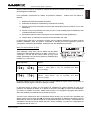
RESET
You can reset the unit without powering off by simultaneously depressing buttons A, B & “ENTER” ()
at the same time.
Selecting cabinet family
Simultaneously depressing A & B buttons at power up or during device RESET accesses the system
change menu. Keep the A & B Buttons held until all LEDs are off. This will allow the selection of any
cabinet in any family. Using the rotary encoder, scroll through the configurations and press “ENTER”
() to load the required settings.
Select your cabinet set-up
In MENU 3.0 you will be able to choose among the different set-ups within the same cabinet family. (i.e.
you don't have to modify the amplifier to cabinet wiring).
Navigating menus
On the controller display screen, the number before the Function corresponds to the menu number. To
change the first number (this is the Main menu label) button A must be pressed. To change the second
number (this is the Submenu label) button B must be pressed. To select options, turn the encoder wheel,
or press the “ENTER” button (). Changes are immediate (no further confirmation unless clearly
stated).
Back to default
In Menu 2.5 you have the possibility to put back all MENUS to the factory default (except the amplifier
information that you have entered MENU 2.6 & 2.7).
Auto save
In case of power failure, the current set-up is saved two minutes after the last change made. At power up
the last saved settings are restored.
USER MANUAL LOAD2_22
DATE: 03/12/2004

ENGLISH
PAGE 8
SETTING-UP ADVICE
Setting-Up Advice
Mains Power
WARNING ! THIS APPLIANCE MUST BE EARTHED.
The green and yellow wire of the mains cord must always be connected to an installation safety earth or
ground. The earth is essential for personal safety as well as the correct installation of the system, and is
internally connected to all exposed metal surfaces. Any rack framework into which this unit may be
mounted is assumed to be connected to the same grounding circuit. (see also p.8)
NEXO TDcontrollers don’t provide a mean to switch off the unit from the front panel. As they are intended
to be rack mounted the back panel is not accessible during use. Therefore it is left to the user to provide a
disconnection mean readily operable.
Voltage setting
NEXO TDcontrollers use a switch mode power supply (SMPS). This SMPS accepts universal AC power
input voltages in the range 90V to 264V, and requires no manual adjustment for voltages in this range.
Mounting the TDcontroller in a rack (Grounding, shielding & safety issues)
The TDcontroller is intended for rack mounting. The only accessible part during use shall be the front
panel of the TDcontroller. Any space above or under the TDcontroller shall be obstructed with a blank
panel.
The rack is a free grounding and shielding structure and it provides extra shielding. Therefore, it is
desirable that the screws used to fix the TDcontroller in the frame or rack provide an electrical contact
between the chassis of the TDcontroller and the rack.
The primary reason for grounding is safety. Conformance to the applicable requirements of the
authorities having jurisdiction is, of course, mandatory. However, grounding also has an impact on
electromagnetic compatibility. From the EMC point of view, it is desirable to have a low impedance
ground network, as a current flowing in the ground network will then produce low voltage in the network.
A low impedance network can be obtained using a multipoint ground scheme, with as many closed
ground loops as is economically possible.
Fuse
The fuse provided in the unit will not blow during normal operation. If the fuse blows the TDcontroller
has malfunctioned. This fuse must only be changed by NEXO certified service personnel. In any case
do not replace the fuse with a non-certified NEXO fuse, as this will invalidate the NEXO warranty.
CAUTION!
This servicing instruction is for use by qualified service personnel only. To reduce the risk of electric
shock, do not perform any servicing other than that contained in the operating instructions unless you are
qualified to do so.
NX242 USER MANUAL LOAD2_22
DATE : 12/3/2004

ENGLISH
PAGE 9
SETTING-UP ADVICE
DATE: 03/12/2004
Recommendations for wiring the sense lines
The impedance of the sense inputs of the TDcontroller are high, so currents are low and therefore light
duty cable can be used. If the TDcontroller is housed in the amplifier racks an unshielded cable may be
used.
If the TDcontroller is located remotely - at the mixing position - a shielded cable is recommended, without
using the shield as a conductor. The cable must be well protected from public access, as it carries
potentially dangerous amplifier voltage.
When one of the channels is not being used and the corresponding sense line is disconnected, cross talk
onto the inactive sense line may in some cases produce signals capable of causing the inadvertent
illumination of the Sense LED on that channel; although this has no effect on the internal operation of the
TDcontroller, it can be cured by short-circuiting the terminals of the inactive sense line.
Recommendations for wiring the audio outputs
The output stages can drive several amplifiers in parallel; however it is not advisable to work with loads of
less than 1kOhm(and strictly forbidden to drive less than 600Ohms). It is best to check the impedance
characteristics of the amplifier inputs - supplied by the manufacturer - to check how many amplifier
channels can be paralleled. Where precise information is not available (and taking 10kOhm as the
minimum value possible), ten channels in parallel per output is a sensible maximum.
Electromagnetic environments
The emission (this word describes all types of electromagnetic noise radiated by the equipment)
requirements which have been applied to Nexo’s TDcontrollers are the stringent requirements of the
”Commercial and light industrial environment” of the product family EMC standard for emission.
The immunity (this word describes the ability to cope with electromagnetic disturbance generated by
other items and natural phenomena) requirements that we have considered exceed those applicable to
the ”Commercial and light industrial environment” of the product family EMC standard for immunity. In
order to provide a further safety margin, we recommend that you do not operate the TDcontrollers in the
presence of electromagnetic interference exceeding half of the limits found in this standard.
Low Z
123
Low Z
123
TDcontroller
AmplifierMixing Desk
123
123
+-
+-
+-
+-
Low Z
Low Z
PE PE
PE
Safety
Ground
SHIELD
SHIELD
IN OUT
These two EMC standards are those applicable to pro-audio equipment for the implementation of the
”EMC directive”.
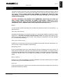
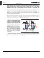
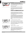
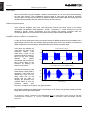
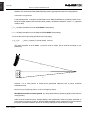
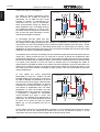
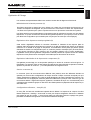
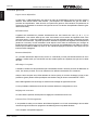
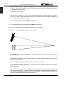
Analogue signal cables
Analogue signals should be connected to the input
and output ports of the TDcontroller via shielded
twisted pair or starquad cable fitted with XLR
connectors on the TDcontroller side. We
recommend the use of low transfer impedance
cables with a braided shield and a transfer
impedance below 10 mΩ/m. For the sense inputs,
the noise requirements are not as stringent, and
any kind of twisted pair cable will be adequate.
The TDcontroller is intended to be used with
USER MANUAL LOAD2_22

ENGLISH
PAGE 10
SETTING-UP ADVICE
symmetrical (balanced) sources (for instance a mixer) and symmetrical loads (for instance a power
amplifier (see figure). You can see that the TDcontroller provides a low impedance path between pin 1 of
its XLR connectors and its chassis. The TDcontroller can sustain high current in pin 1 without
degradation of output noise. We recommend that the sources and loads you use have the same
desirable characteristics.
It is sometimes claimed that connecting cable shield at both ends creates ground loops, and that the
current flowing in such loops will produce noise. This is not the case for most professional audio
equipment. In short, there are two kinds of loops in which voltages are present: the loops formed by
signal wires, and the loops formed by grounded conductors, among which are protective earth
conductors (PE) and signal cable shields.
When a cable shield is grounded at both ends, a loop is closed, and the resulting current causes a
reduction of the voltage induced on signal lines. This effect is what the cable shield is intended to
produce, since this is how it protects your signal from magnetic fields.
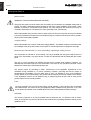
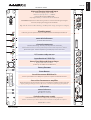
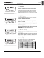
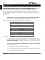
If you are using an asymmetrical
(unbalanced) source (not recommended),
it is best to use a shielded twisted pair and
to connect wire 3 of the cable to the shield
at the source output end (see figure). This
technique prevents noise currents flowing
on the return path of the signal. If you are
using an amplifier with an asymmetrical
(unbalanced) input, it is best to use a
shielded twisted pair, and to connect wire 3
at the TDcontroller end only, as shown in
Fig. 2. This keeps a good capacitance
balance for the signal, however noise
currents flow on the return path of the
signal. (Note that this is only acceptable for
a short cable).
Low Z
123
Low Z
123
TDcontroller
AmplifierMixing Desk
123
123
+-
+-
+-
+-
Low Z ?
Low Z ?
?PE
PE
Safety
Ground
SHIELD
SHIELD
0V
IN OUT
If you are using a symmetrical (balanced) source or amplifier which is prone to become noisy when a
current of less than 100 mA at the mains frequency (50 Hz or 60 Hz) is sourced into pin 1 of its XLR
connectors, you might consider opening the ground loops.
NX242 USER MANUAL LOAD2_22
DATE : 12/3/2004

ENGLISH
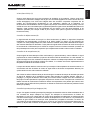
PAGE 11
SETTING-UP ADVICE
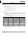
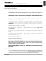
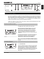
SENSE INPUT
(from amp terminals)
BALANCED OUTPUTS
+ 4
-
+ 3
-
+ 2
-
+ 1
-
RS23
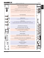
FLOATING BALANCED INPUTS
Channel 4 Channel 3 Channel 2 Channel1 B (RIGHT) A (LEFT)
MADE IN FRANCE
115 - 230V 50 - 60Hz 45W
CAUTION !
To reduce the risk of electric schock, grounding
of the center pin of this plug must be maintained.
NX242
CAUTION - RISK OF FIRE
DO NOT OPEN
NX242 TDcontroller
03105
sept.04
I
N
T
32
N
A
L
A
GeoT 4805-2815
Crossover 75Hz
Hi
g
h end Floatin
g
balanced Input
Maximum Clippin
g
input : 28dBu
N
omina
l
Input impe
d
ance : 19.8
k
O
hm
Common Mo
d
e Ratio (CMRR): 85
d
B
Very High Immunity to common mode inter
f
erences
HEADROOM ad
j
ustement allows the signal to be scaled to the Analogue to Digital
Converter, keeping the unit
y
gain of the NX242
Hig
h
en
d
AD converter :24
b
it a
ll
owing a 110
d
B Dynamic range (ana
l
ogue to ana
l
ogue
)
B
lank
i
ng panel
I
n t
h
is s
l
ot goes t
h
e optiona
l
NXtension-CAI an
d
NXtension-ES4 Expan
d
er Boar
d
s
.
H
eav
y
Dut
y
Balanced Output Stage
.
Hig
h
en
d
DA 24
b
it convertion
D
e
l
ivers up to 28
d
Bu into 600O
h
m
l
oa
d
Ser
i
al Connect
i
on RS232 to P
C
C
onnect
y
our NX242 to the COM port of
y
our PC to update the NX242 Firmware.
Sense Line Connector to amplifier
Allows the best use o
f
the protection process, including the ampli
f
ier analysis (gain and
cl
ipping vo
l
tage). Fai
l
ing to connect t
h
e sense connector may
d
amage your spea
k
ers.
Switch mode power supply
Detac
h
a
bl
e Power cor
d
s
h
a
ll
comp
l
y wit
h
your country regu
l
ation.
All
ows continuous operation
b
etween 90V an
d
260V. No A
d
justment require
d
.
O
N
/
OFF Mains Switc
h
M
ute & Solo Buttons
R
ed LED : Muted Channe
l
C
hannel mon
i
tor
i
ng
R
ed LED Peak Limiting : Prevent your ampli
f
ier
f
rom overloadin
g
Y
ellow LED Protections : Prevent s
p
eaker Dis
p
lacement and Tem
p
erature failure
s
Green LED Signal : Monitor amplifier signal & displa
y
s sense error alerts.
LCD contrast ad
j
ustmen
t
I
n
p
ut Overload / DSP Cli
p
Rotary Enco
d
er
En
t
er
Butto
n
M
enu Select
i
o
n
Sub
Men
u
B
S
ele
ct
i
on
Main Menu A Selection
L
C
D screen
ss
48
USER MANUAL LOAD2_22
DATE: 03/12/2004

ENGLISH
PAGE 12
GENERAL DESCRIPTION
GENERAL DESCRIPTION
Global architecture
Global architecture is based upon a full 24bit audio path with 48bit core calculator running at 100 Million
Instructions per Second. Featuring:
2 analogue inputs (floating balanced) 24bit resolution ADC.
4 analogue outputs (balanced) 24bit resolution DAC.
4 sense inputs (balanced) 16bit resolution ADC.
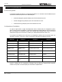
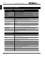
Set-up configurations
The audio path is automatically adjusted within the NX242 according to the setups (PS15, GEOT, CD18)
chosen by the user. This will affect the delays and gain control. For instance changing the gain of a CD18
cabinet will affect two channels at a time, changing the gain on a 3 WAY cabinet (e.g. Alpha) will affect
three channels, etc.
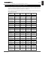
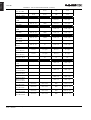
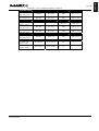
At the time of writing, the following configurations are used (for a complete description Appendix A on
page 37 for the list of setups currently supported)
Channel 1 Channel 2 Channel 3 Channel 4
unused unused 2 WAY Passive Cabinet 2 WAY Passive Cabinet
Channel 2 duplicated Sub 2 WAY Passive Cabinet 2 WAY Passive Cabinet
Sub Sub 2 WAY Passive Cabinet 2 WAY Passive Cabinet
1WAY Active cabinet 1WAY Active cabinet 1WAY Active cabinet 1WAY Active cabinet
unused 1WAY Active cabinet 1WAY Active cabinet 1WAY Active cabinet
Cardioid back Cardioid front Active cabinet unused
Cardioid back Cardioid front Active cabinet Channel 2 duplicated
Cardioid Sub 1 back Cardioid Sub 1 front Cardioid Sub 2 back Cardioid Sub 2 front
You may have noticed that certain configuration (4 passive cabinets for instance) are not supported.
Using those configurations requires the addition of the optional NXtension Expander Board. Please refer
to the separate manual for additional information.
NX242 USER MANUAL LOAD2_22
DATE : 12/3/2004

ENGLISH
PAGE 13
BLOCK DIAGRAM DESCRIPTION
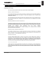
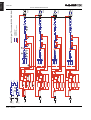
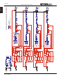
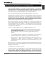
Block diagram description
Equalisation & Filtering
The number between parenthesis refers to the number circled in the block diagram.
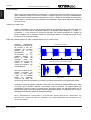
Subsonic and VHF filtering (1)
Low and high-pass filters are used to filter out frequency components that could possibly degrade the
performance of the TDcontroller and amplifiers. The filters are optimised to work in conjunction with
overall system response.
The high pass filters are also extremely important as they optimise excursion at very low frequency which
is a very important safety factor. (Therefore do not use set-ups which are not designed for the cabinet
you are using).
Equalising wideband acoustical response (2)
This wideband equaliser section achieves the correction required to obtain a flat system response, as the
cabinets are acoustically designed for maximum efficiency on the whole frequency range. Active rather
than passive attenuation allows the lowering of amplifier voltages for a given output SPL and therefore
increases the maximum SPL achievable with the same amplifier.
Active equalisation also extends system bandpass especially at low frequencies where acoustical
performance is limited by cabinet size.
Equalising single component response (3)
This equaliser set allows acting on a specific driver after the crossover, rather than the on wideband
section. This allows to EQ one driver without affecting the others (cleaning out of band response, fine
tuning in a crossover…). All the parameters are factory set.
Crossover section (4)
Crossover between different bands is tuned for every set-up of every cabinet. Each crossover is
customized so that each transducer will fit with its neighbour by achieving a perfect phase alignment.
Unconventional, crossover-defined filters are applied, ranging from 6dB/octave to near infinite slopes
according to the type of crossover desired. Time alignment is also unconventionally achieved, by
combining crossover filter group delays with allpass and/or frequency dependent delays.
User set-up, Array EQ (5)
A basic Array EQ is currently implemented in the NX242. The cut off frequency of a low-shelving filter is
factory tuned for each cabinet set-up. The user has access to the gain of this filter. The array EQ is tuned
in order to reproduce the effect of the bass coupling, allowing the user to increase or diminish the effect of
the stacking.
USER MANUAL LOAD2_22
DATE: 03/12/2004

ENGLISH
PAGE 14
BLOCK DIAGRAM DESCRIPTION
3
R+L
2
L
1
R
Voice Coil Temp.
ChassisTemp
Command
PHYSIO 4
Voice Coil Temp.
ChassisTemp
Command
PHYSIO 3
Voice Coil Temp.
ChassisTemp
Command
PHYSIO 2
Voice Coil Temp.
ChassisTemp
Command
PHYSIO 1
Command
PEAK SIMULATION 4
Command
PEAK SIMULATION 3
Command
PEAK SIMULATION 2
Command
PEAK SIMULATION
PATCH 4
PATCH 3
PATCH 2
PATCH
Disp.
Command
Voice Coil Temp.
ChassisTemp.
LF TEMPERATURE 4
Disp.
Command
Voice Coil Temp.
ChassisTemp.
LF TEMPERATURE 3
Disp.
Command
Voice Coil Temp.
ChassisTemp.
LF TEMPERATURE 2
Disp.
Command
Voice Coil Temp.
ChassisTemp.
LF TEMPERATURE
0
INPUT VU-METER
0
A/D EQ
A/D
DACMUTEEQ
EQ
A/D DACMUTEEQ
EQ
A/D
SHELVING
DACMUTEEQ
EQ
A/D DACMUTEEQ
EQ
SHELVING
A/D EQ
Command
HF TEMPERATURE 4
Command
HF TEMPERATURE 3
Command
HF TEMPERATURE 2
Command
HF TEMPERATURE
VCA
VCA
VCA
VCA
FALLBACK
AMP VOLTAGE
Signal
AMP POWER
AMP GAIN
FALLBACK
AMP VOLTAGE
Signal
AMP POWER
AMP GAIN
FALLBACK
AMP VOLTAGE
Signal
AMP POWER
AMP GAIN
FALLBACK
AMP VOLTAGE
Signal
AMP POWER
AMP GAIN
Command
displacement
DISPLACEMENT 4
Command
displacement
DISPLACEMENT 3
Command
displacement
DISPLACEMENT 2
Command
displacement
DISPLACEMENT 1
DELAY 4
DELAY 3
DELAY 2
DELAY 1
ATT/REL.3
ATT/REL.2
ATT/REL.1
ATT/REL.
2
L
3
R+L
1
R
2
L
3
R+L
1
R
2
L 1
3
R+L 1
8
SENSE 4
7
SENSE 3
6
SENSE 2
5
SENSE 1
1
R 1
2
L
3
R+L
1
R
INPUT VU-METER
INPUT R
INPUT L
OUTPUT
CHANNEL 4
OUTPUT
CHANNEL 3
OUTPUT
CHANNEL 2
OUTPUT CHANNEL 1
NX242 Digital TDcontroller BLOCK DIAGRAM
Analogue path
Digital Audio
Digital servo & protections
HEADROOM
HEADROOM
1
2
3 3
4
4
5
6
7 7
8
9
9
10
11
12
13
NX242 USER MANUAL LOAD2_22
DATE : 12/3/2004

ENGLISH
PAGE 15
BLOCK DIAGRAM DESCRIPTION
Protection
VCAs (6) and VCEQs (7)
Each channel has its own simulation and protection process.
Each audio channel contains a combination of controlled gain stages (let's call them VCA’s as in our
analogue circuitry). These VCA's are embedded into complex composite structures in order to change
their basic operation into frequency selective attenuation. This operation is similar to that of a voltage
controlled dynamic equaliser (VCEQ).
Each VCEQ and VCA is controlled by the synthesis of several signals issued from the various detection
sections. That synthesis is in fact the envelope of those signals, with an optimised release and attack
time for each VCEQ and VCA (depending on its frequency range and the cabinet selected).
Displacement control (8)
The sense input signal is sent to a shaping filter producing a signal whose instantaneous amplitude is
proportional to the voice coil excursion. This signal, after rectification, is compared to a preset threshold
matching the maximum usable value, as determined from laboratory measurements.
Any part of the signal exceeding the threshold is sent to the VCEQ control buffer while the VCEQ acts as
an instantaneous limiter (very short attack time) to prevent displacement from overriding the maximum
permissible value.
Temperature control (9)
Each sense signal is fed into a shaping filter (one per transducer), each one producing a signal
proportional to the instantaneous current flowing into the voice coil of the transducer. After rectification,
this signal is integrated with attack and release time constants equivalent to the thermal time constants of
the voice coil and chassis, producing a voltage, which is representative of the instantaneous temperature
of the voice coil.
When this voltage reaches the threshold value corresponding to the maximum safe operation
temperature, the VCA becomes active to reduce the Audio signal level and limit the effective temperature
to fall under the maximum usable value.
In order to avoid detrimental effects induced by very long release time constants coming from the
temperature detection signal (level being reduced for an extended period, « pumping » effects...), the
detection signal is modulated by another voltage integrated with faster time constants matching the
sound level subjective perception. This allows the controller to reduce the effective operation duration of
the temperature limiter and make it sound more natural, while the efficiency of protection is fully
preserved and operation thresholds are unaffected (kept as high as possible).
Physiologic Dynamic Control (10)
The so-called Physiologic Dynamic Control is intended to avoid unwanted effects as a result of a too long
attack time constant. By anticipating the operation of the temperature limiter, it prevents a high level
Audio signal appearing suddenly then being kept up for a period, which is long enough to trigger the
temperature limiter. Without this, a rough and delayed gain variation would result which would be quite
noticeable and unnatural.
USER MANUAL LOAD2_22
DATE: 03/12/2004

ENGLISH
PAGE 16
BLOCK DIAGRAM DESCRIPTION
The Physio control voltage acts independently on the VCA with its operation threshold slightly lower (3
dB) that of the temperature limiter and a low compression ratio; its optimised attack time constant allows
it to start operating without any subjectively unpleasant transient effects.
Interchannel regulation (11)
As described before, each transducer is individually servo-controlled for temperature.
This means in practice that, in case of a potential risk detected, protective operation would only affect the
concerned driver. Your driver will be protected but the overall system tonal balance could be altered if the
different channels are not heating at the same time. In addition, triggering a temperature protection
means that the loudspeaker has already lost some efficiency (power compression up to 3dB in extreme
cases)
The purpose of interchannel regulation is to cancel that effect by linking VCAs together. When the
protection is activated on one channel and reaches a predetermined threshold, the regulation section
begins to correct the balance between the different channels (HF, MF, and LF) by acting on the
concerned VCA.
Peak limiter (12)
The peak limiter primary function is to avoid massive clipping of the amp, which can have some very
audible artefacts.
The threshold of the peak limiter is determined by the user to match its amplifier. See in “ Amplifiers
(Gain, Power)” page 25.
The second function of the peak limiter is to avoid huge amounts of power being sent to a driver. Each
driver is protected in temperature and displacement but there could be other factors of destruction that
cannot be predicted by simulation (especially mechanical damage to the cone…). Each driver is specified
for a certain power handling and a factory set peak limiter threshold is tuned to avoid any abuse.
Delay & polarity inversion (13)
Input to output delay without filtering is 2.2ms (due to the digital processing). The latency time of the
NX241 used to be 1.4ms. Since the LOAD2_21 the latency time of the NX241 has been artificially
extended to 2.2ms to achieve phase compatibility with the NX242 (and so the delay between the 2 units
is less than a sample). For that reason: Do not mix NX241 with a LOAD earlier to 2.20 with the NX242
This delay will prevent also compatibility with analogue TDcontrollers.
ANALOGUE AND DIGITAL
TDCONTROLLER SHOULD NOT BE MIXED IN THE SAME SYSTEM.
Factory set-up delay
Note that each output may contain a small phase adjustment delay at the crossover point. Also, a polarity
inversion may be performed. These adjustments are part of the factory set-ups and are necessary to
time-align the corresponding cabinet that is selected.
NX242 USER MANUAL LOAD2_22
DATE : 12/3/2004

ENGLISH
PAGE 17
BLOCK DIAGRAM DESCRIPTION
User set-up delay
Following user delay adjustment is possible:
GLOBAL: Affecting all channels at the same time (delaying all the system for application as delay
towers…)
MAIN: Affecting only the channels driving the MAIN system (differ in case of TWO cabinet or 3WAY
cabinet)
SUB: Affecting only the channels driving the SUB system.
GLOBAL and MAIN/SUB delays are cumulative up to 150m per channel (about 450ms, 500 feet).
Audio Input/Output
See also the wiring recommendations in the “setting up advices” section, at the beginning of this manual.
Floating balanced audio input
A new ruggedized, truly floating, high-end performance Input stage has been developed for the NX242.
In the max HEADROOM position, it is accepting input level up to 28dBu and keeping this performance
when driven by unbalanced impedance sources or when submitted to high common mode level.
The analogue inputs are on 3 pin female XLR connectors with positive and negative signal polarities on
pins 2 and 3 respectively. Pin 1 is directly coupled to the chassis.
The input signal can be adjusted in MENU 1.1 HEADROOM in order to avoid clipping of the A/D
converter. See corresponding paragraph (MENU section page 19)
Balanced audio output
The analogue outputs are on 3-pin male XLR connectors with positive and negative signal polarities on
pins 2 and 3 respectively. Pin 1 is directly coupled to the chassis. The output will deliver a full-scale output
of +28dBu(balanced 600 / 1nF load.)
During A/C power up of the NX242, all outputs are muted by firmware-controlled relays (strapping pin 2
and pin 3 of each output).
USER MANUAL LOAD2_22
DATE: 03/12/2004

ENGLISH
PAGE 18
BLOCK DIAGRAM DESCRIPTION
General functions
Remote sense lines
Line input (–18dB less than the amplifier gain) is allowing
remote sensing. You will need to use this
function to have an 18dB gain attenuator near the amplifier. This function enables you to keep the
TDcontroller at the mixing position and still being able to feed an attenuated amplifier voltage (for safety
reasons) to the sense line connector.
Reset
Holding down the three menu buttons (A, B, ) simultaneously will reset the unit. Reset has the same
effect as powering on and off the unit. The unit will mute (hardware) for 5 seconds with all LED’s on. The
unit will then return to the last set-up automatically saved (every 2 minutes).
Resetting the unit from the front panel is needed to change the cabinet family (Press the three buttons to
reset then let go of the ENTER button to enter into MENU 0). In that case you will have to keep the A & B
Buttons until all LEDs light off.
Mute/Solo buttons
Front panel, direct access. The Mute (or Solo) mode is selected in the user menu. Please note that these
MUTEs are soft mute and are therefore not operating output relays.
Display & Indicators
User control of all settings is via two menu scroll pushbuttons, an additional assignable pushbutton, an
assignable rotary encoder and a backlit 16*2 character display.
Three LED’s per channel for sense (green), peak limit (red) protects (yellow). Four dedicated LED’s are
situated alongside the associated MUTE/SOLO button.
Two LED’s to indicate input overload and signal clipping into the DSP.
Default screen will pop up after 2 minutes and display the current set-up.
Contrast adjustment
A hole in the front panel allows the adjustment of the contrast of the LCD screen.
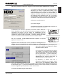
Serial link / Downloader
The unit can be RS232 linked to any PC in order to download new versions of Firmware using a
Windows compatible Downloader program. See corresponding chapter page 32.
NX242 USER MANUAL LOAD2_22
DATE : 12/3/2004

ENGLISH
PAGE 19
MENU DESCRIPTION
-- LOAD2_20 --
(c) NEXO 2004
MENU DESCRIPTION
On the controller display screen, the number before the Function corresponds to the Menu Number. To
change the first number (this is the Main menu label) button A must be pressed. To change the second
number (this is the Submenu label) button B must be pressed. To select options, turn the encoder wheel,
or press the ENTER button (). Changes are immediate (no validation is required unless clearly
stated).
Please refer to the release notes issued with each new download to track eventual menu changes.
USER MANUAL LOAD2_22
DATE: 03/12/2004
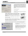
Main Family Selection
Changing Cabinet Family
In order to prevent end-user changing between different
NEXO system set-ups during use, the following procedure
is obligatory. This procedure has been purposely designed
to avoid any mistake. It is nevertheless very easy to
change set-up among the same family (see menu 3)
Depressing A & B buttons while the NX242 is resetting.
You can reset the unit without powering off by
simultaneously depressing buttons A, B & ENTER () at
the same time.
Note: Selecting a new family will set all parameters to
factory default settings.
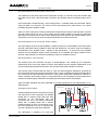
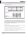
User settings
1.1 HEADROOM
Allows the user to adjust the headroom (8 steps, 3dB each)
before the A/D converter without changing the overall gain
of the processor. Factory default is set to maximum
headroom (and so, maximum noise). This can be adjusted
if you feel the processor is too noisy for lower level
applications.
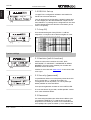
An Input bar graph meter displays input level and
headroom before input clip. The maximum of the left and
right input is shown on the meter. Note that the meter does
not show DSP clipping.

ENGLISH
PAGE 20
MENU DESCRIPTION
NX242 USER MANUAL LOAD2_22
DATE : 12/3/2004
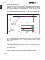
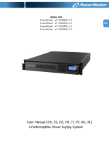
The input meter is accessed through the MENU 1.1
(HEADROOM) by depressing ENTER WX button. Press
the ENTER WX button to toggle between the meter and
the normal HEADROOM screen. Note: In meter mode, the
default screen is not activated.
The meter also pops up automatically when the signal is
above a certain threshold.
The red arrow above illustrates the Headroom available
before clipping of the input converters of the NX242. The
dynamic range of the meter is 24 dB. The scale is given
below; maximum being 0dBFS (the red LED marked ‘in
clip’ will light).
-3-6-12-24
A permanent peak hold allows you to see if input clipping
has reached. Changing the headroom (by turning the
wheel) resets the peak hold indication. You can also reset
the peak hold (without changing the headroom) by pressing
the enter WX button twice.
To set the HEADROOM correctly, feed a typical example of
the loudest desired program level into the NX242. Reduce
the Headroom by turning the wheel anti-clockwise until the
INPUT LED or DSP LED indicates the NX242 has reached
clipping. Then go one click backwards (turn the wheel
clockwise). The signal should now be clearly visible on the
meter scale, but without reaching the right-hand end of the
display.
1.2 DELAYS [Sub / Main / Global]
Each output channel can be delayed by up to a maximum
(global + individual delay) of 450ms (150m). See page 17
The unit can display in [FEET / METRES / SECONDS] as
required. Delay is adjustable in 10cm (0.3ms) increments.
The control pot will accelerate through the adjustments
faster according to the speed of use.
1.3 OUT Levels
[Global / HF /MF / LF / SUB]]
Adjust overall & separate TDcontroller gain with this menu.
These gain controls are provided to adjust the tonal
balance of the system by acting on separate channels. You
can also compensate for gain differences between different
amplifiers. (Although the use of differing gain structure
amplifiers in the same set-up is possible it is not
recommended).
Each of the individual or global gain is +/- 6dB. (Step
Strona się ładuje...
Strona się ładuje...
Strona się ładuje...
Strona się ładuje...
Strona się ładuje...
Strona się ładuje...
Strona się ładuje...
Strona się ładuje...
Strona się ładuje...
Strona się ładuje...
Strona się ładuje...
Strona się ładuje...
Strona się ładuje...
Strona się ładuje...
Strona się ładuje...
Strona się ładuje...
Strona się ładuje...
Strona się ładuje...
Strona się ładuje...
Strona się ładuje...
Strona się ładuje...
Strona się ładuje...
Strona się ładuje...
Strona się ładuje...
Strona się ładuje...
Strona się ładuje...
Strona się ładuje...
Strona się ładuje...
Strona się ładuje...
Strona się ładuje...
Strona się ładuje...
Strona się ładuje...
Strona się ładuje...
Strona się ładuje...
Strona się ładuje...
Strona się ładuje...
Strona się ładuje...
Strona się ładuje...
Strona się ładuje...
Strona się ładuje...
Strona się ładuje...
Strona się ładuje...
Strona się ładuje...
Strona się ładuje...
Strona się ładuje...
Strona się ładuje...
Strona się ładuje...
Strona się ładuje...
Strona się ładuje...
Strona się ładuje...
Strona się ładuje...
Strona się ładuje...
Strona się ładuje...
Strona się ładuje...
Strona się ładuje...
Strona się ładuje...
-
 1
1
-
 2
2
-
 3
3
-
 4
4
-
 5
5
-
 6
6
-
 7
7
-
 8
8
-
 9
9
-
 10
10
-
 11
11
-
 12
12
-
 13
13
-
 14
14
-
 15
15
-
 16
16
-
 17
17
-
 18
18
-
 19
19
-
 20
20
-
 21
21
-
 22
22
-
 23
23
-
 24
24
-
 25
25
-
 26
26
-
 27
27
-
 28
28
-
 29
29
-
 30
30
-
 31
31
-
 32
32
-
 33
33
-
 34
34
-
 35
35
-
 36
36
-
 37
37
-
 38
38
-
 39
39
-
 40
40
-
 41
41
-
 42
42
-
 43
43
-
 44
44
-
 45
45
-
 46
46
-
 47
47
-
 48
48
-
 49
49
-
 50
50
-
 51
51
-
 52
52
-
 53
53
-
 54
54
-
 55
55
-
 56
56
-
 57
57
-
 58
58
-
 59
59
-
 60
60
-
 61
61
-
 62
62
-
 63
63
-
 64
64
-
 65
65
-
 66
66
-
 67
67
-
 68
68
-
 69
69
-
 70
70
-
 71
71
-
 72
72
-
 73
73
-
 74
74
-
 75
75
-
 76
76


Nexo NX242 Instrukcja obsługi
- Kategoria
- Wzmacniacze dźwięku
- Typ
- Instrukcja obsługi
w innych językach
- čeština: Nexo NX242 Uživatelský manuál
- español: Nexo NX242 Manual de usuario
- italiano: Nexo NX242 Manuale utente
- Deutsch: Nexo NX242 Benutzerhandbuch
- svenska: Nexo NX242 Användarmanual
- português: Nexo NX242 Manual do usuário
- français: Nexo NX242 Manuel utilisateur
- Türkçe: Nexo NX242 Kullanım kılavuzu
- English: Nexo NX242 User manual
- dansk: Nexo NX242 Brugermanual
- русский: Nexo NX242 Руководство пользователя
- Nederlands: Nexo NX242 Handleiding
- română: Nexo NX242 Manual de utilizare
Powiązane artykuły
Inne dokumenty
-
Yamaha n12 Instrukcja obsługi
-
Limit LM400 Karta katalogowa
-
-
Focal ALPHA EVO Instrukcja obsługi
-
 PowerWalker VFI 2000 RM LCD Instrukcja obsługi
-
Iomega REV LOADER Instrukcja obsługi
-
Naim DAC-V1 Skrócona instrukcja obsługi
-
-
AEM 30-2841 Instrukcja obsługi
-
