Yamaha RX-300 Instrukcja obsługi
- Kategoria
- Odbiorca
- Typ
- Instrukcja obsługi
Ten podręcznik jest również odpowiedni dla

OWNER’S MANUAL
MODE D’EMPLOI
BEDIENUNGSANLEITUNG
BRUKSANVISNING
MANUALE DI ISTRUZIONI
MANUAL DE INSTRUCCIONES
GEBRUIKSAANWIJZING
Natural Sound AV Receiver
Récepteur audiovisuel “Son Naturel”
Natural Sound AV-Receiver
Natural Sound AV-receiver
Sintonizzatore AV a suono naturale
Receptor AV de Sonido Natural
Natural Sound AV Ontvanger
R X-V493RDS
R X-V393RDS
G B

2
●
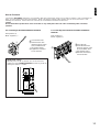
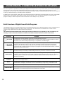
Indoor FM Antenna
●
Antenne FM intérieure
●
UKW-Innenantenne
●
FM inomhusantenn
●
Antenna FM interna
●
Antena FM interior
●
FM Binnenantenne
●
AM Loop Antenna
●
Cadre-antenne AM
●
MW-Rahmenantenne
●
AM ramantenn
●
Antenna AM ad anello
●
Antena de cuadro de AM
●
AM Lusantenne
●
75-ohm/300-ohm antenna adapter (U.K. model only)
●
Adaptateur d’antenne 75 ohms/300 ohms (Modèle pour le
Royaume-Uni seulement)
●
75 Ohm/300 Ohm Antennenstecker (nur Großbritannien-
Modell)
●
75 ohm/300 ohm antennadapter (Endast modell för
Storbritannien)
●
Adattatore per antenna da 75 e 300 ohm (Solo modello per
la Gran Bretagna)
●
Adaptador de antena de 75 ohmios/300 ohmios (Modelo
para Reino Unido sólo)
●
75 ohm/300 ohm antenne-adapter (Alleen modellen voor
Groot-Brittannië)
●
Remote Control Transmitter
●
Télécommande
●
Fernbedienung
●
Fjärrkontroll
●
Telecomando
●
Transmisor de control remoto
●
Afstandbediening
●
Batteries (size AA, R6, UM-3)
●
Piles (taille AA, R6, UM-3)
●
Batterien (Größe AA, R6, UM-3)
●
Batterier (storlek AA, R6, UM-3)
●
Batterie (dimensioni AA, R6, UM-3)
●
Pilas (tamaño AA, R6, UM-3)
●
Batterijen (maat AA, R6, UM-3)
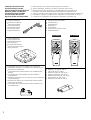
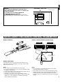
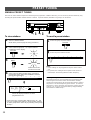
SUPPLIED ACCESSORIES
●
After unpacking, check that the following parts are included.
ACCESSOIRES FOURNIS
●
Après le déballage, vérifier que les pièces suivantes sont incluses.
MITGELIEFERTE ZUBEHÖRTEILE
●
Nach dem Auspacken überprüfen, ob die folgenden Teile vorhanden sind.
MEDFÖLJANDE TILLBEHÖR
●
Kontrollera efter det apparaten packats upp att följande delar finns med.
ACCESSORI IN DOTAZIONE
●
Verificare che tutte le parti seguenti siano contenute nell’imballaggio dell’apparecchio.
ACCESORIOS INCLUIDOS
●
Desembalar el aparato y verificar que los siguientes accesorios están en la caja.
BIJGELEVERDE ACCESSOIRES
●
Controleer na het uitpakken of de volgende onderdelen voorhanden zijn.
2CH
/6CH
REC/PAUSE
DIR BDIR A
PLAY
DISC
VOLUME
PLAY
PRESET
A/B/C/D/E
–+
TESTDELAY TIME
EFFECT
PROGRAM
PROLOGIC
ENHANCED
–+
SLEEP
TAPE
A/B
ON/OFF
TUNER
CD
PHONO
VIDEO
VCR
POWER /I
REC/PAUSE
DIR BDIR A
PLAY
DISC
POWER /I
VOLUME
PLAY
PRESET
A/B/C/D/E
–+
TIME/
LEVEL
TEST
EFFECT
PROGRAM
PROLOGIC
ENHANCED
–+
SLEEP
TAPE
A/B
ON/OFF
2CH
/6CH
TUNER
CD
PHONO
DELAY/CENTER
/REAR/SWFR
DVD/LD
VCR
TV/DBS
RX-V493RDS RX-V393RDS

3
English
●
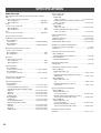
5 Speaker Configuration
(Power Amp. Section)
RX-V493RDS
Main:
65W + 65W (8Ω) RMS Output
Power, 0.04% THD, 20–20,000 Hz
Center: 65W (8Ω) RMS Output Power,
0.04% THD, 1 kHz
Rear: 20W + 20W (8Ω) RMS Output
Power, 0.04% THD, 1 kHz
RX-V393RDS
Main: 50W + 50W (8Ω) RMS Output
Power, 0.04% THD, 20–20,000 Hz
Center: 50W (8Ω) RMS Output
Power, 0.04% THD, 1 kHz
Rear: 20W + 20W (8Ω) RMS Output
Power, 0.04% THD, 1 kHz
●
Digital Sound Field Processor
●
Dolby Pro Logic Surround Decoder
●
Theater-like Sound Experience by the
Combination of Dolby Pro Logic and
YAMAHA DSP Technology (CINEMA DSP)
●
Automatic Input Balance Control for
Dolby Pro Logic Surround
●
Test Tone Generator for Easier Speaker
Balance Adjustment
●
3 Center Channel Modes
(NORMAL/WIDE/PHANTOM)
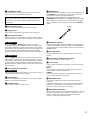
● Multi-Functions for RDS Broadcast
Reception
● 40-Station Random Access Preset Tuning
● Automatic Preset Tuning
● Preset Station Shifting Capability (Preset
Editing)
● IF Count Direct PLL Synthesizer Tuning
System
● 6-Channel Discrete Input Terminals for
Connecting with a Dolby Digital (AC-3)
Decoder
● Video Signal Input/Output Capability
● SLEEP Timer
● Remote Control Capability
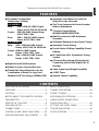
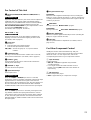
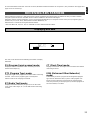
SUPPLIED ACCESSORIES ...........................2
FEATURES .....................................................3
CAUTION ........................................................4
NOTES ABOUT THE REMOTE CONTROL
TRANSMITTER ...............................................5
PROFILE OF THIS UNIT ................................6
SPEAKER SETUP ..........................................7
CONNECTIONS ..............................................8
CONTROLS AND THEIR FUNCTIONS ........16
SPEAKER BALANCE ADJUSTMENT ..........22
BASIC OPERATIONS ...................................25
TUNING OPERATIONS ................................29
PRESET TUNING .........................................30
RECEIVING RDS STATIONS ........................33
USING DIGITAL SOUND FIELD
PROCESSOR (DSP) ....................................38
SETTING THE SLEEP TIMER ......................42
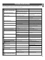
TROUBLESHOOTING ..................................43
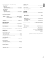
SPECIFICATIONS .........................................44
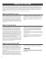
Thank you for selecting this YAMAHA AV receiver.
FEATURES
CONTENTS

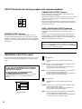
4
1. To assure the finest performance, please read this manual
carefully. Keep it in a safe place for future reference.
2. Install this unit in a cool, dry, clean place – away from
windows, heat sources, sources of excessive vibration,
dust, moisture and cold. Avoid sources of humming
(transformers, motors). To prevent fire or electrical shock,
do not expose the unit to rain or water.
3. Never open the cabinet. If something drops into the set,
contact your dealer.
4. Do not use force on switches, controls or connection wires.
When moving the unit, first disconnect the power plug and
the wires connected to other equipment. Never pull the
wires themselves.
5. The openings on the cabinet assure proper ventilation of
the unit. If these openings are obstructed, the temperature
inside the cabinet will rise rapidly. Therefore, avoid placing
objects against these openings, and install the unit in well-
ventilated condition. Be sure to allow a space of at least
20 cm behind, 20 cm on the both sides and 30 cm above
the top panel of the unit. Otherwise it may not only damage
the unit, but also cause fire.
6. Always set the VOLUME control to “–
∞
” before starting
the audio source play. Increase the volume gradually to an
appropriate level after playback has been started.
7. Do not attempt to clean the unit with chemical solvents;
this might damage the finish. Use a clean, dry cloth.
8. Be sure to read the “TROUBLESHOOTING” section
regarding common operating errors before concluding that
the unit is faulty.
9. When not planning to use this unit for long periods of time
(ie., vacation, etc.), disconnect the AC power plug from the
wall outlet.
10.To prevent lightning damage, disconnect the AC power
plug and antenna cable when there is an electrical storm.
11.Grounding or polarization – Precautions should be taken
so that the grounding or polarization of an appliance is not
defeated.
12.Do not connect audio equipment to the AC outlet on the
rear panel if the equipment requires more power than the
outlet is rated to provide.
This unit is not disconnected from the AC power source as
long as it is connected to the wall outlet, even if this unit
itself is turned off. This state is called the standby mode.
In this state, this unit is designed to consume a very small
quantity of power.
IMPORTANT
Please record the serial number of this unit in the space
below.
Model:
Serial No.:
The serial number is located on the rear of the unit.
Retain this Owner’s Manual in a safe place for future
reference.
WARNING
TO REDUCE THE RISK OF FIRE OR ELECTRIC SHOCK,
DO NOT EXPOSE THIS UNIT TO RAIN OR MOISTURE.
For U.K. customers
If the socket outlets in the home are not suitable for the plug
supplied with this appliance, it should be cut off and an
appropriate 3 pin plug fitted. For details, refer to the
instructions described below.
Note: The plug severed from the mains lead must be
destroyed, as a plug with bared flexible cord is hazardous if
engaged in a live socket outlet.
Special Instructions for U.K. Model
IMPORTANT
THE WIRES IN MAINS LEAD ARE COLOURED IN
ACCORDANCE WITH THE FOLLOWING CODE:
Blue: NEUTRAL
Brown: LIVE
As the colours of the wires in the mains lead of this
apparatus may not correspond with the coloured markings
identifying the terminals in your plug, proceed as follows:
The wire which is coloured BLUE must be connected to the
terminal which is marked with the letter N or coloured
BLACK. The wire which is coloured BROWN must be
connected to the terminal which is marked with the letter L
or coloured RED. Making sure that neither core is
connected to the earth terminal of the three pin plug.
CAUTION : READ THIS BEFORE OPERATING YOUR UNIT.

5
English
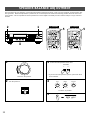
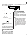
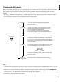
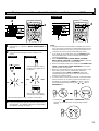
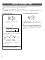
Battery installation
Battery replacement
If you find that the remote control transmitter must be used
closer to the main unit, the batteries are weak. Replace both
batteries with new ones.
Notes
●
Use only AA, R6, UM-3 batteries for replacement.
●
Be sure the polarities are correct. (See the illustration inside
the battery compartment.)
●
Remove the batteries if the remote control transmitter will not
be used for an extended period of time.
●
If batteries leak, dispose of them immediately. Avoid
touching the leaked material or letting it come in contact with
clothing, etc. Clean the battery compartment thoroughly
before installing new batteries.
Remote control transmitter operation range
Notes
●
There should be no large obstacles between the remote
control transmitter and the main unit.
●
If the remote control sensor is directly illuminated by strong
lighting (especially an inverter type of fluorescent lamp etc.),
it might cause the remote control transmitter not to work
correctly. In this case, reposition the main unit to avoid direct
lighting.
1
3
2
RX-V393RDS
RX-V493RDS
NOTES ABOUT THE REMOTE CONTROL TRANSMITTER
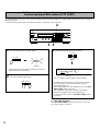
WARNING
Do not change the IMPEDANCE SELECTOR switch
setting while the power to this unit is on, otherwise this
unit may be damaged.
IF THIS UNIT FAILS TO TURN ON WHEN THE
STANDBY/ON SWITCH IS PRESSED
The IMPEDANCE SELECTOR switch may not be set to
either end closely. If so, set the switch to either end closely.
l6
20
28
40
60
l2
8
4
2
0
–dB
l6
20
28
40
60
l2
8
4
2
0
–dB
30°
30°
Remote control
sensor
Within approximately
6 m (19.7 feet)
IMPEDANCE SELECTOR
(Europe model)
REAR
CENTER
MAIN
6
Ω
MIN. /SPEAKER
SINGLE
:
6
Ω
MIN. /SPEAKER
DUAL
:3
Ω
MIN. /SPEAKER
A OR B
:4
Ω
MIN. /SPEAKER
A B
:8
Ω
MIN. /SPEAKER
REAR
CENTER
MAIN
8
Ω
MIN. /SPEAKER
SINGLE
:
8
Ω
MIN. /SPEAKER
DUAL
:4
Ω
MIN. /SPEAKER
A OR B
:8
Ω
MIN. /SPEAKER
A B
:16
Ω
MIN. /SPEAKER
IMPEDANCE SELECTOR
SET BEFORE POWER ON

6
PROFILE OF THIS UNIT
You are the proud owner of a Yamaha stereo receiver –an extremely sophisticated audio component. The Digital Sound Field
Processor (DSP) built into this unit takes advantage of Yamaha’s undisputed leadership in the field of digital audio processing to
bring you a whole new world of listening experiences. Follow the instructions in this manual carefully when setting up your system,
and this unit will sonically transform your room into a wide range of listening environments –movie theater, concert hall, and so on.
In addition, you get incredible realism from sources encoded with Dolby Surround using the built-in Dolby Pro Logic Surround
Decoder.
Please read this operation manual carefully and store it in a safe place for later reference.
Digital Sound Field Processing
What is it that makes live music so good? Today’s advanced
sound reproduction technology lets you get extremely close to
the sound of a live performance, but chances are you’ll still
notice something missing: the acoustic environment of the live
concert hall. Extensive research into the exact nature of the
sonic reflections that create the ambience of a large hall has
made it possible for Yamaha engineers to bring you this same
sound in your own listening room, so you’ll feel all the sound of
a live concert.
Furthermore, our technicians, armed with sophisticated
measuring equipment, have even made it possible to capture
the acoustics of a variety of venues such as an actual concert
hall, theater, etc. to allow you to accurately recreate one of
several actual live performance environments, all in your own
home.
Dolby Pro Logic Surround
This unit employs a Dolby Pro Logic Surround decoder similar
to professional Dolby Stereo decoders used in many movie
theaters. By using the Dolby Pro Logic Surround decoder, you
can experience the dramatic realism and impact of Dolby
Surround movie theater sound in your own home. Dolby Pro
Logic employs a four channel five speaker system. The Pro
Logic Surround system divides the input signal into four levels:
the left and right main channels, the center channel (used for
dialog), and the rear surround sound channels (used for sound
effects, background noise, and other ambient noises). The
center channel allows listeners seated in even less-than-ideal
positions to hear the dialog originating from the action on the
screen while experiencing good stereo imaging.
Dolby Surround is encoded on the sound track of pre-recorded
video tapes, laser discs, and some TV/cable broadcasts. When
you play a source encoded with Dolby Surround on this unit,
the Dolby Pro Logic Surround decoder decodes the signal and
distributes the surround-sound effects.
This Dolby Pro Logic Surround Decoder employs a digital
signal processing system. This system improves the stability of
sound at each channel and minimizes crosstalk between
channels, so that positioning of sounds around the room is
more accurate compared with conventional analog signal
processing systems.
In addition, this unit features a built-in automatic input balance
control. This always assures you the best performance without
manual adjustment.
Manufactured under license from Dolby Laboratories Licensing
Corporation. “Dolby”, “AC-3”, “Pro Logic” and the double-D
symbol are trademarks of Dolby Laboratories Licensing
Corporation.
Dolby Pro Logic Surround + DSP
Dolby Surround sound system shows its full ability in a large
movie theater, because movie sounds are originally designed
to be reproduced in a large movie theater using many
speakers. It is difficult to create a sound environment similar to
that of a movie theater in your listening room, because the
room size, materials of inside walls, the number of speakers,
etc. of your listening room is much different from those of a
movie theater.
Yamaha DSP technology made it possible to present you with
nearly the same sound experience as that of a large movie
theater in your listening room by compensating for lack of
presence and dynamics in your listening room with its original
digital sound fields combined with Dolby Surround sound field.
The combination of Dolby Pro Logic Surround and DSP is used
on the sound field program “ PRO LOGIC ENHANCED”.
The YAMAHA “CINEMA DSP” logo indicates these programs are
created by the combination of Dolby Pro Logic and YAMAHA
DSP technology.
CINEMA DSP

7
English
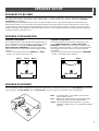
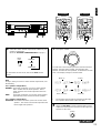
SPEAKER SETUP
SPEAKERS TO BE USED
This unit is designed to provide the best sound-field quality with a 5 speaker configuration. The most effective speakers to use with
this unit are main speakers, rear speakers and a center speaker. You may omit the center speaker. (Refer to the “4-Speaker
Configuration” shown below.)
The main speakers are used for the main source sound plus the effect sounds. They will probably be the speakers from your
present stereo system. The rear speakers are used for the effect and surround sounds, and the center speaker is for the center
sounds (dialog etc.) within programs encoded with Dolby Surround. The center speaker needs to be equal in power to the main
speakers, although the rear speakers should not be equal. However, all the speakers should have high enough power handling to
accept the maximum output of this unit.
SPEAKER CONFIGURATION
5-Speaker Configuration
This configuration is the most effective and recommended one.
In this configuration, the center speaker is necessary as well as
the rear speakers. If the program DOLBY PRO LOGIC or
DOLBY PRO LOGIC ENHANCED is selected, conversations
will be output from the center speaker and the ambience will be
excellent.
• Set the center channel mode to the “NORMAL” or “WIDE”
position. (For details, refer to page 23.)
4-Speaker Configuration
The center speaker is not used in this configuration. If the
program DOLBY PRO LOGIC or DOLBY PRO LOGIC
ENHANCED is selected, the center sound is output from the
left and the right main speakers. However, the sound effect of
other programs can be the same as that of the 5-speaker
configuration.
• Be sure to set the center channel mode to the “PHANTOM”
position. (For details, refer to page 23.)
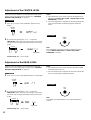
SPEAKER PLACEMENT
The recommended speaker configuration, the 5-speaker configuration, will require two speaker pairs: main speakers (your normal
stereo speakers), and rear speakers, plus a center speaker. When you place these speakers, refer to the following.
Main: In normal position. (The position of your present
stereo speaker system.)
Rear: Behind your listening position, facing slightly inward.
Nearly 1.8m (approx. 6 feet) up from the floor.
Center: Precisely between the main speakers. (To avoid
interference with TV sets, use a magnetically shielded
speaker.)
Front L Center Front R
Dialogue
Surround sound
Dialogue
Surround sound
Rear L
Rear R
Front L Front R
Dialogue
Surround sound
Dialogue
Surround sound
Rear L Rear R
Front R
Center
Front L
TV set
Rear R
Rear L
Main L
Main R
Main L
Main R
Main L
Main R

8
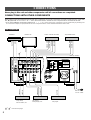
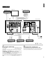
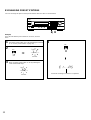
CONNECTIONS
Never plug in this unit and other components until all connections are completed.
CONNECTIONS WITH OTHER COMPONENTS
When making connections between this unit and other components, be sure all connections are made correctly, that is to say L (left)
to L, R (right) to R, “+” to “+” and “–” to “–”. Also, refer to the owner’s manual for each component to be connected to this unit.
* If you have YAMAHA components numbered as 1, 3, 4, etc. on the rear panel, connections can be made easily by making sure
to connect the output (or input) terminals of each component to the same-numbered terminals of this unit.
*
1
,
*
2
: See the next page.
FM
ANT
AM
ANT
GND
75Ω
UNBAL.
GND
MONITOR OUT
DVD/LD TV/DBS
IN OUT
VCR
IN OUT
VCR
PHONO
CD
DVD/LD TV/DBS
TAPE
PB
REC
OUT
1
3 4
REAR
CENTER
MAIN
6
Ω
MIN. /SPEAKER
SINGLE
:
6
Ω
MIN. /SPEAKER
DUAL
:3
Ω
MIN. /SPEAKER
A OR B
:4
Ω
MIN. /SPEAKER
A B
:8
Ω
MIN. /SPEAKER
REAR
CENTER
MAIN
8
Ω
MIN. /SPEAKER
SINGLE
:
8
Ω
MIN. /SPEAKER
DUAL
:4
Ω
MIN. /SPEAKER
A OR B
:8
Ω
MIN. /SPEAKER
A B
:16
Ω
MIN. /SPEAKER
DVD/LD
TV/DBS
MAIN
R L
SURROUND
R L
CENTER
SUB
WOOFER
6CH
DISCRETE
INPUT
VIDEO
SIGNAL
TAPE
/MD
AUDIO SIGNAL
IMPEDANCE SELECTOR
SET BEFORE POWER ON
I00W MAX. TOTAL
SWITCHED
AC OUTLETS
SEE INSTRUCTION MANUAL FOR CORRECT SETTING
.
MAIN
A
B
CENTER
REAR
(SURROUND)
OUTPUT
SUB
WOOFER
SPEAKERS
10dB 0dB
MAIN
LEVEL
GND
OUTPUT
AUDIO IN
VIDEO IN
AUDIO OUT
VIDEO OUT
VIDEO IN
AUDIO OUT
VIDEO OUT
LINE OUT
LINE IN
OUTPUT
VIDEO OUT
AUDIO OUT
(Europe model)
To AC outlet
Turntable
LD player,
DVD player, etc.
Video cassette recorder
TV/Satellite tuner
Tape deck,
MD recorder, etc.
CD player
Monitor TV
*
2
*
1
RX-V493RDS

9
English
AC OUTLETS (SWITCHED)
(Europe model) ................................. 2 SWITCHED OUTLETS
(U.K. model) ........................................ 1 SWITCHED OUTLET
Use these to connect the power cords from your components
to this unit.
The power to the SWITCHED outlets is controlled by this unit’s
STANDBY/ON switch or the provided remote control
transmitter’s POWER /I key. These outlets will supply power
to any component whenever this unit is turned on.
The maximum power (total power consumption of components)
that can be connected to the SWITCHED AC OUTLETS is 100
watts.
GND terminal (For turntable use)
Connecting the ground wire of the turntable to the GND
terminal will normally minimize hum, but in some cases better
results may be obtained with the ground wire disconnected.
*
1
*
2
RX-V393RDS
FM
ANT
AM
ANT
GND
75Ω
UNBAL.
GND
MONITOR OUT
VIDEO
IN OUT
VCR
IN OUT
VCR
PHONO
CD
VIDEO
TAPE
PB
REC
OUT
1
3 4
REAR
CENTER
MAIN
6
Ω
MIN. /SPEAKER
SINGLE
:
6
Ω
MIN. /SPEAKER
DUAL
:3
Ω
MIN. /SPEAKER
A OR B
:4
Ω
MIN. /SPEAKER
A B
:8
Ω
MIN. /SPEAKER
REAR
CENTER
MAIN
8
Ω
MIN. /SPEAKER
SINGLE
:
8
Ω
MIN. /SPEAKER
DUAL
:4
Ω
MIN. /SPEAKER
A OR B
:8
Ω
MIN. /SPEAKER
A B
:16
Ω
MIN. /SPEAKER
VIDEO
MAIN
R L
SURROUND
R L
CENTER
SUB
WOOFER
6CH
DISCRETE
INPUT
VIDEO
SIGNAL
TAPE
/MD
AUDIO SIGNAL
IMPEDANCE SELECTOR
SET BEFORE POWER ON
I00W MAX. TOTAL
SWITCHED
AC OUTLETS
SEE INSTRUCTION MANUAL FOR CORRECT SETTING
.
MAIN
A
B
CENTER
REAR
(SURROUND)
OUTPUT
SUB
WOOFER
SPEAKERS
10dB 0dB
MAIN
LEVEL
GND
OUTPUT
AUDIO IN
VIDEO IN
AUDIO OUT
VIDEO OUT
VIDEO IN
LINE OUT
LINE IN
OUTPUT
VIDEO OUT
AUDIO OUT
(Europe model)
To AC outlet
Turntable
LD player,
DVD player, etc.
Video cassette recorder
Tape deck,
MD recorder, etc.
CD player
Monitor TV
*
2
*
1
*
1
,
*
2
: See below.

FM
ANT
AM
ANT
GND
75Ω
UNBAL.
GND
MONITOR OUT
DVD/LD TV/DBS
IN OUT
VCR
IN OUT
VCR
PHONO
CD
DVD/LD TV/DBS
TAPE
PB
REC
OUT
1
3 4
DVD/LD
TV/DBS
MAIN
R L
SURROUND
R L
CENTER
SUB
WOOFER
6CH
DISCRETE
INPUT
VIDEO
SIGNAL
TAPE
/MD
AUDIO SIGNAL
AC-3 RF
OUT
AC-3 RF
IN
DIGITAL
IN
DIGITAL
OUT
VIDEO OUT
AUDIO OUT
6CH DISCRETE OUTPUT
CENTER SURROUNDMAIN
SUB
WOOFER
10dB 0dB
MAIN
LEVEL
10
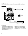
Connecting with 6 channel discrete outputs of a Dolby digital (AC-3) decoder
or a DVD player, etc.
If you have a Dolby Digital (AC-3) decoder or a DVD player etc. which incorporates a Dolby Digital (AC-3) decoder or a DTS
decoder, its 6 channel discrete outputs can be connected to the 6CH DISCRETE INPUT terminals of this unit.
Notes for RX-V493RDS
• The laserdisc player (or another unit) must be also
connected to the DVD/LD (or TV/DBS) AUDIO SIGNAL input
terminals of this unit for playing a source with the Dolby Pro
Logic Surround decoded or in normal stereo (or monaural).
• The discrete signals input to this unit cannot be recorded by
a tape deck, MD recorder or VCR. To record a source played
on the laserdisc player (or another unit), it must be
connected to the DVD/LD (or TV/DBS) AUDIO/VIDEO
SIGNAL input terminals of this unit.
• If you made no connection to the SUBWOOFER input
terminal of this unit or you will not use a subwoofer, you
should make a setting for distributing signals at the
SUBWOOFER channel to the right and left MAIN output
terminals on the Dolby Digital (AC-3) decoder etc.
For details, refer to the owner’s manual for the Dolby Digital
(AC-3) decoder etc.
Dolby Digital (AC-3) decoder
RF Demodulator
Laserdisc player with AC-3 RF output or
another unit
RX-V493RDS
(Example)

FM
ANT
AM
ANT
GND
75Ω
UNBAL.
GND
MONITOR OUT
VIDEO
IN OUT
VCR
IN OUT
VCR
PHONO
CD
VIDEO
TAPE
PB
REC
OUT
1
3 4
VIDEO
MAIN
R L
SURROUND
R L
CENTER
SUB
WOOFER
6CH
DISCRETE
INPUT
VIDEO
SIGNAL
TAPE
/MD
AUDIO SIGNAL
AC-3 RF
OUT
AC-3 RF
IN
DIGITAL
IN
DIGITAL
OUT
VIDEO OUT
AUDIO OUT
6CH DISCRETE OUTPUT
CENTER SURROUNDMAIN
SUB
WOOFER
10dB 0dB
MAIN
LEVEL
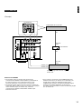
11
English
Notes for RX-V393RDS
• The laserdisc player (or another unit) must be also
connected to the VIDEO AUDIO SIGNAL input terminals of
this unit for playing a source with the Dolby Pro Logic
Surround decoded or in normal stereo (or monaural).
• The discrete signals input to this unit cannot be recorded by
a tape deck, MD recorder or VCR. To record a source played
on the laserdisc player (or another unit), it must be
connected to the VIDEO AUDIO/VIDEO SIGNAL input
terminals of this unit.
• If you made no connection to the SUBWOOFER input
terminal of this unit or you will not use a subwoofer, you
should make a setting for distributing signals at the
SUBWOOFER channel to the right and left MAIN output
terminals on the Dolby Digital (AC-3) decoder etc.
For details, refer to the owner’s manual for the Dolby Digital
(AC-3) decoder etc.
Dolby Digital (AC-3) decoder
RF Demodulator
Laserdisc player with AC-3 RF output or
another unit
RX-V393RDS
(Example)

12
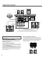
CONNECTING SPEAKERS
CENTER
REAR
(SURROUND)
OUTPUT
SUB
WOOFER
REAR
CENTER
CD
DUAL
SINGLE
CAUTION
SEE INSTRUCTION MANUAL FOR CORRECT SETTING
.
MAIN
A
B
REAR
CENTER
MAIN
6
Ω
MIN. /SPEAKER
SINGLE
:
6
Ω
MIN. /SPEAKER
DUAL
:3
Ω
MIN. /SPEAKER
A OR B
:4
Ω
MIN. /SPEAKER
A B
:8
Ω
MIN. /SPEAKER
REAR
CENTER
MAIN
8
Ω
MIN. /SPEAKER
SINGLE
:
8
Ω
MIN. /SPEAKER
DUAL
:4
Ω
MIN. /SPEAKER
A OR B
:8
Ω
MIN. /SPEAKER
A B
:16
Ω
MIN. /SPEAKER
SPEAKERS
IMPEDANCE SELECTOR
SET BEFORE POWER ON
Rear speaker Rear speaker
Center speaker
Main speakers B
Left
Right
Left
Right
Main speakers A
Subwoofer system
Left
Right
Note
Use speakers with the specified impedance shown on the
rear of this unit.
Note on main speaker connections:
One or two speaker systems can be connected to this unit. If
you use only one speaker system, connect it to either the
SPEAKERS A or B terminals.
Note on a subwoofer connection:
You may wish to add a subwoofer to reinforce low frequencies
or to output low bass sound from the subwoofer channel when
reproducing discrete signals.
Connect the SUBWOOFER OUTPUT terminal of this unit to
the INPUT terminal of the subwoofer amplifier, and connect the
speaker terminals of the subwoofer amplifier to the subwoofer.
With some subwoofers, including the Yamaha Active Servo
Processing Subwoofer System, the amplifier and subwoofer
are in the same unit.
Note on center speaker connection:
One or two center speakers can be connected to this unit. If
you cannot place the center speaker on or under the TV, it is
recommended to use two center speakers and place them on
both sides of the TV to orient the center sound at the center
position. For connecting two center speakers, follow the
method shown below.
REAR
CENTER
CD
DUAL
SINGLE
Center speaker
Center speaker
(Europe model)

13
English
For connecting to the MAIN SPEAKERS terminals
Red: positive (+)
Black: negative (–)
➀
Unscrew the knob.
➁
Insert the bare wire.
[Remove approx. 5mm
(1/4”) insulation from
the speaker wires.]
➂
Tighten the knob and
secure the wire.
For connecting to the REAR and CENTER SPEAKERS
terminals
Red: positive (+)
Black: negative (–)
➀
Press the tab.
➁
Insert the bare wire.
[Remove approx. 5mm
(1/4”) insulation from
the speaker wires.]
➂
Release the tab and
secure the wire.
1
2
3
How to Connect:
Connect the SPEAKERS terminals to your speakers with wire of the proper gauge, cut as short as possible. If the connections are
faulty, no sound will be heard from the speakers. Make sure that the polarity of the speaker wires is correct, that is the + and –
markings are observed. If these wires are reversed, the sound will be unnatural and lack bass.
Caution
Do not let the bare speaker wires touch each other or any metal part of this unit. This could damage this unit and/or
speakers.
MAIN LEVEL switch
Normally set to “0 dB”. If desired, you can decrease the
output level at the MAIN SPEAKERS terminals by 10 dB by
setting this switch to “–10 dB”.
FM
ANT
AM
ANT
GND
75Ω
UNBAL.
GND
PHONO
TAPE
PB
3
MAIN
LEVEL
10dB 0dB
➁
➂
➀

14
CENTER OUTPUT terminal
This terminal is for center channel line output. There is no
connection to this terminal when you use the built-in amplifier.
However, if you drive a center speaker with an external power
amplifier, connect the input terminal of the external amplifier to
this terminal.
SUBWOOFER OUTPUT terminal
This terminal is for connecting with the input terminal of an
amplifier for driving a subwoofer.
This terminal outputs low frequencies from the main and center
channels. (The cut-off frequency of signals output from this
terminal is 150 Hz.)
When 6 channel discrete signals are input to this unit and are
selected as the input source, this terminal outputs signals from
the subwoofer channel.
REAR (SURROUND) OUTPUT terminals
These terminals are for rear channel line output. There is no
connection to these terminals when you use the built-in
amplifier.
However, if you drive rear speakers with an external stereo
power amplifier, connect the input terminals of the external
amplifier (MAIN IN or AUX terminals of a power amplifier or an
integrated amplifier) to these terminals.
Note
Output level of signals from these terminals are adjusted
by the use of VOLUME control on the front panel or VOLUME
keys on the remote control transmitter.
OUTPUT terminals (for driving speakers with external amplifiers)
Be sure to switch this only when the power to this unit is not on.
Select the position whose requirements your speaker system
meets.
(Upper position)
Rear: The impedance of each speaker must be 6Ω or
higher.
Center: If you use one center speaker, the impedance of the
speaker must be 6Ω or higher.
If you use two center speakers, the impedance of
each speaker must be 3Ω or higher.
Main: If you use one pair of main speakers, the impedance
of each speaker must be 4Ω or higher.
If you use two pairs of main speakers, the impedance
of each speaker must be 8Ω or higher.
(Lower position)
Rear: The impedance of each speaker must be 8Ω or
higher.
Center: If you use one center speaker, the impedance of the
speaker must be 8Ω or higher.
If you use two center speakers, the impedance of
each speaker must be 4Ω or higher.
Main: If you use one pair of main speakers, the impedance
of each speaker must be 8Ω or higher.
If you use two pairs of main speakers, the impedance
of each speaker must be 16Ω or higher.
IMPEDANCE SELECTOR switch
REAR
CENTER
MAIN
6
Ω
MIN. /SPEAKER
SINGLE
:
6
Ω
MIN. /SPEAKER
DUAL
:3
Ω
MIN. /SPEAKER
A OR B
:4
Ω
MIN. /SPEAKER
A B
:8
Ω
MIN. /SPEAKER
REAR
CENTER
MAIN
8
Ω
MIN. /SPEAKER
SINGLE
:
8
Ω
MIN. /SPEAKER
DUAL
:4
Ω
MIN. /SPEAKER
A OR B
:8
Ω
MIN. /SPEAKER
A B
:16
Ω
MIN. /SPEAKER
IMPEDANCE SELECTOR
SET BEFORE POWER ON
CENTER
REAR
(SURROUND)
OUTPUT
SUB
WOOFER
(Europe model)
WARNING
Do not change the IMPEDANCE SELECTOR switch
setting while the power to this unit is on, otherwise
this unit may be damaged.
IF THIS UNIT FAILS TO TURN ON WHEN THE
STANDBY/ON SWITCH IS PRESSED
The IMPEDANCE SELECTOR switch may not be set to
either end closely. If so, set the switch to either end
closely.

15
English
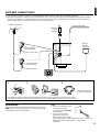
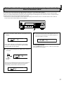
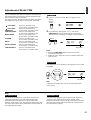
ANTENNA CONNECTIONS
●
Each antenna should be connected to the designated terminals correctly, referring to the following diagram.
●
Both AM and FM indoor antennas are included with this unit. In general, these antennas will probably provide sufficient signal
strength. Nevertheless, a properly installed outdoor antenna will give clearer reception than an indoor one. If you experience
poor reception quality, an outdoor antenna may result in improvement.
Connecting the AM loop antenna
* The AM loop antenna should be placed apart from the main unit. The antenna may be hung on a wall.
* The AM loop antenna should be kept connected, even if an outdoor AM antenna is connected to this unit.
GND terminal
For maximum safety and minimum interference, connect the
GND terminal to a good earth ground. A good earth ground is
a metal stake driven into moist earth.
Notes
●
When connecting the indoor
FM antenna, insert its
connector into the FM ANT
terminal firmly.
●
If you need an outdoor
FM antenna to improve
FM reception quality, either
300-ohm feeder or coaxial cable may be used. In locations
troubled by electrical interference, coaxial cable is
preferable.
FM
ANT
AM
ANT
GND
75Ω
UNBAL.
➀
➁
➂
Orient so that the best
reception is obtained.
1 2 3
Outdoor FM antenna
Outdoor AM antenna
AM loop
antenna
(included)
Ground
75-ohm/300-ohm
antenna adapter
75-ohm/300-ohm
antenna adapter
75-ohm coaxial cable
300-ohm feeder
Indoor FM
antenna
(included)

16
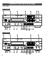
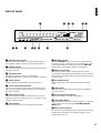
CONTROLS AND THEIR FUNCTIONS
FRONT PANEL
PRO LOGIC
ENHANCED
CONCERT
VIDEO
MONO
MOVIE
STADIUM
STANDBY/ON
NATURAL SOUND AV RECEIVER
RX–V493RDS
SPEAKERSPHONES
A
ON
B
OFF
BASS TREBLE BALANCE
VOLUME
55
4
3
2
l
0
l
2
3
4
55
4
3
2
l
0
l
2
3
4
LR
l6
20
28
40
60
l2
8
4
2
0
–dB
CINEMA DSP
55
4
3
2
l
0
l
2
3
4
DELAY/CENTER
/REAR/SWFR
FM
/
AM
MAN'L
/
AUTO FM
TUNING
MODE
AUTO
/
MAN'L MONO
CENTER
MODE
DISCO
CONCERT
HALL
ROCK
CONCERT
EFFECT
DOWN
TUNING
UP
MEMORY
EDIT
TIME
/
LEVEL
A
/
B
/
C
/
D
/
E
1
2 3 4 5 6 7 8
VCR DVD
/
LDTV
/
DBS
TAPE/MD MON 2CH/6CH
TUNER
CD
PHONO
1
89 0 A B C IJL MN
H
K
23 45 76
RDS MODE/FREQ
EON
MODE
START
PTY SEEK
DEF
G
STANDBY/ON
NATURAL SOUND AV RECEIVER
RX–V393RDS
SPEAKERSPHONES
A
ON
B
OFF
BASS TREBLE BALANCE
VOLUME
55
4
3
2
l
0
l
2
3
4
55
4
3
2
l
0
l
2
3
4
LR
l6
20
28
40
60
l2
8
4
2
0
–dB
CINEMA DSP
55
4
3
2
l
0
l
2
3
4
FM
/
AM
MAN'L
/
AUTO FM
TUNING
MODE
AUTO
/
MAN'L MONO
CENTER
MODE
DOWN
TUNING
UP
EFFECT
MEMORY
EDIT
PROGRAM
A
/
B
/
C
/
D
/
E
1
2 3 4 5 6 7 8
TAPE/MD
MONITOR
VIDEO
2CH/6CH
VCR
TUNER
CD
PHONO
REAR
LEVEL
CENTER
LEVEL
0l0 0l0
1
89 0 A B C O
P QN
6
23 4 7
IJL
H
K
RDS MODE/FREQ
EON
MODE
START
PTY SEEK
DEF
G
RX-V493RDS
RX-V393RDS

17
English
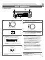
1 STANDBY/ON switch
Press this switch to turn the power to this unit on. Press it
again to turn this unit into the standby mode.
Standby mode
In this state, this unit consumes a very small quantity of
power to receive infrared-signals from the remote control
transmitter.
2 Remote control sensor
Receives signals from the remote control transmitter.
3 Display panel
Shows various information. (For details, refer to page 19.)
4 Input selector buttons
Select a program source to listen to or watch. When a button is
pressed, the name of selected source appears on the display.
RX-V493RDS only
When the TV/DBS or DVD/LD input source is selected,
pressing the same button (TV/DBS or DVD/LD) switches the
input signals between 2 channel stereo signals and 6 channel
discrete signals. When switched to “6ch”, discrete signals from
the unit connected to the 6CH DISCRETE INPUT DVD/LD
TV/DBS terminals of this unit are selected as the input signals.
RX-V393RDS only
When the VIDEO input source is selected, pressing the same
button (VIDEO) switches the input signals between 2 channel
stereo signals and 6 channel discrete signals. When switched
to “6ch”, discrete signals from the unit connected to the 6CH
DISCRETE INPUT VIDEO terminals of this unit are selected as
the input signals.
5 DSP program selector buttons
RX-V493RDS only
Select a DSP program. When a button is pressed, the name of
selected program lights up on the display.
6 EFFECT button
Switches on/off the digital sound field processor (including the
Dolby Pro Logic Surround decoder).
7 VOLUME control
Used to raise or lower the volume level.
8 PHONES jack
When you listen with headphones, connect the headphones to
the PHONES jack. You can listen to the sound to be output
from the main speakers through headphones.
When listening with headphones privately, set both the
SPEAKERS A and B switches to the OFF position and switch
off the digital sound field processor (so that no DSP program
name is illuminated on the display) by pressing the EFFECT
button.
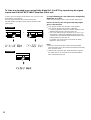
9 SPEAKERS switches
Set the switch A or B (or both A and B) for the main speaker
system (connected to this unit) you will use to the ON position.
Set the switch for the main speaker system you will not use to
the OFF position.
0 A/B/C/D/E button
Press this button to select a desired group (A–E) of preset
stations.
A Preset station number selector buttons
Select a preset station number (1 to 8).
B Tone controls
These controls are effective only for the sound from the main
speakers.
BASS
Used to increase or decrease the low frequency response.
The 0 position produces flat response.
TREBLE
Used to increase or decrease the high frequency response.
The 0 position produces flat response.
C BALANCE control
This control is effective only for the sound from the main
speakers.
Adjusts the balance of the output volume to the left and right
speakers to compensate for sound imbalance caused by
speaker location or listening room conditions.
D RDS MODE/FREQ button
When an RDS station is received, pressing this button changes
the display mode into the PS mode, PTY mode, RT mode
and/or CT mode (if the station employs those RDS data
services), and frequency display in turn.
PHONES

18
E PTY SEEK MODE button
When this button is pressed, the unit turns into the PTY SEEK
mode.
F PTY SEEK START button
Press this button to begin searching for a station after the
desired program type is selected in the PTY SEEK mode.
G EON button
Press this button to select a desired program type (NEWS,
INFO, AFFAIRS, SPORT) when you want to call a radio
program of that program type automatically.
H FM/AM button
Press this button to switch the reception band to FM or AM.
I MEMORY (MAN’L/AUTO FM) button
When this button is pressed, the
“
MEMORY” indicator flashes
for about 5 seconds. During this period, select a desired
preset station number by pressing the corresponding preset
station number selector button to enter the displayed station
into the memory.
When this button is pressed and held for more than 3 seconds,
the automatic preset tuning begins. (For details, refer to page
31.)
J EDIT button
This button is used to exchange the places of two preset
stations with each other.
K TUNING DOWN/UP button
Used for tuning. Press the “UP” side to tune in to higher
frequencies, and press the “DOWN” side to tune in to lower
frequencies.
When this unit is in the PTY SEEK mode, pressing this switch
changes the currently selected program type.
L TUNING MODE (AUTO/MAN’L MONO) button
Press this button to switch the tuning mode to automatic or
manual. To select the automatic tuning mode, press this
button so that the “AUTO” indicator lights up on the display. To
select the manual tuning mode, press this button so that the
“AUTO” indicator goes off.
M DELAY/CENTER/REAR/SWFR and TIME/LEVEL +/–
buttons
RX-V493RDS only
Adjust the delay time (DELAY), the center channel output level
(CENTER), the rear channel output level (REAR) and the
output level to the SUBWOOFER OUTPUT terminal (SWFR).
Select the item which you want to adjust by pressing the
DELAY/CENTER/REAR/SWFR button and adjust its time or
level by pressing the TIME/LEVEL +/– button.
N CENTER MODE button
Selects a center channel output mode (NORMAL, WIDE or
PHANTOM). (For details, refer to page 23.)
O PROGRAM selector button
RX-V393RDS only
When the built-in digital sound field processor (including the
Dolby Pro Logic Surround decoder) is on, this button changes
the currently selected DSP program whenever the right or left
side of this button is pressed.
P CENTER LEVEL control
RX-V393RDS only
Adjusts the sound output level of the center speaker.
Q REAR LEVEL control
RX-V393RDS only
Adjusts the sound output level of the rear speakers.

19
English
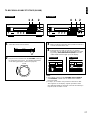
DISPLAY PANEL
1 Multi-information display
Displays various information, for example station frequency,
preset station number and name of selected input source.
2 STEREO indicator
Lights up when an FM stereo broadcast with sufficient signal
strength is received.
3 Signal-level meter
Indicates the signal level of the received station.
If multipath interference is detected, the indication decreases.
4 SLEEP indicator
Lights up while the built-in SLEEP timer is functioning.
5 Center channel mode indicators
The name of a selected center channel mode lights up only
when a program which uses the Dolby Pro Logic Surround
decoder is selected.
6 EFFECT OFF indicator
Lights up if neither the digital sound field processor nor the
Dolby Pro Logic Surround decoder is on. In this state, sound
output is 2-channel stereo.
7 AUTO indicator
Lights up when this unit is in the automatic tuning mode.
8 MEMORY indicator
When the MEMORY button is pressed, this indicator flashes
for about 5 seconds. During this period, the displayed station
can be programmed to the memory by using the A/B/C/D/E
button and the preset station number selector buttons.
9 RDS mode indicators
The name(s) of RDS mode(s) employed by the currently
received RDS station light(s) up. Illumination of the indicator on
the head of a name shows that the corresponding RDS mode
is now selected.
0 PTY HOLD indicator
Lights up while the search is performed in the PTY SEEK
mode.
A EON indicator
Lights up when an RDS station that employs the EON data
service is received.
B Program type name indicators
The name selected in the EON mode lights up.
C TAPE MON indicator
Lights up when the tape deck (or MD recorder etc.) is selected
as the input source by pressing the TAPE/MD MONITOR
(MON) button.
D DSP program indicators
The name of a selected DSP program lights up when the built-
in digital sound field processor and/or the Dolby Pro Logic
Surround decoder is on.
PRESET
kHz
MHz
MEMORY
AUTO PTY HOLD
SLEEP
TAPE MON
STEREO
0
20
l00
ms dB
PRO LOGIC
ENHANCED
CONCERT
VIDEO
MONO
MOVIE
STADIUM
DISCO
ROCK CONCERT
CONCERT HALL
NORM
WIDE
PHANTOM
EFFECT OFF
PS
EON
AFFAIRS SPORT
NEWS INFO
RT CTPTY
123
56
C
D
A0B978
4

20
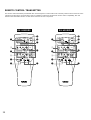
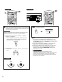
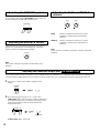
REMOTE CONTROL TRANSMITTER
The remote control transmitter provided with this unit is designed to control all the most commonly used functions of this unit. If the
CD player and tape deck connected to this unit are YAMAHA components designed for remote control compatibility, then this
remote control transmitter will also control various functions of each component.
REC/PAUSE
DIR BDIR A
PLAY
DISC
POWER /I
VOLUME
PLAY
PRESET
A/B/C/D/E
–+
TIME/
LEVEL
TEST
EFFECT
PROGRAM
PROLOGIC
ENHANCED
–+
SLEEP
TAPE
A/B
ON/OFF
2CH
/6CH
TUNER
CD
PHONO
DELAY/CENTER
/REAR/SWFR
DVD/LD
VCR
TV/DBS
2
3
4
2
8
9
6
7
5
1
1
2CH
/6CH
REC/PAUSE
DIR BDIR A
PLAY
DISC
VOLUME
PLAY
PRESET
A/B/C/D/E
–+
TESTDELAY TIME
EFFECT
PROGRAM
PROLOGIC
ENHANCED
–+
SLEEP
TAPE
A/B
ON/OFF
TUNER
CD
PHONO
VIDEO
VCR
2
3
4
2
8
9
6
7
5
1
1
POWER /I
RX-V393RDS
RX-V493RDS
Strona jest ładowana ...
Strona jest ładowana ...
Strona jest ładowana ...
Strona jest ładowana ...
Strona jest ładowana ...
Strona jest ładowana ...
Strona jest ładowana ...
Strona jest ładowana ...
Strona jest ładowana ...
Strona jest ładowana ...
Strona jest ładowana ...
Strona jest ładowana ...
Strona jest ładowana ...
Strona jest ładowana ...
Strona jest ładowana ...
Strona jest ładowana ...
Strona jest ładowana ...
Strona jest ładowana ...
Strona jest ładowana ...
Strona jest ładowana ...
Strona jest ładowana ...
Strona jest ładowana ...
Strona jest ładowana ...
Strona jest ładowana ...
Strona jest ładowana ...
Strona jest ładowana ...
-
 1
1
-
 2
2
-
 3
3
-
 4
4
-
 5
5
-
 6
6
-
 7
7
-
 8
8
-
 9
9
-
 10
10
-
 11
11
-
 12
12
-
 13
13
-
 14
14
-
 15
15
-
 16
16
-
 17
17
-
 18
18
-
 19
19
-
 20
20
-
 21
21
-
 22
22
-
 23
23
-
 24
24
-
 25
25
-
 26
26
-
 27
27
-
 28
28
-
 29
29
-
 30
30
-
 31
31
-
 32
32
-
 33
33
-
 34
34
-
 35
35
-
 36
36
-
 37
37
-
 38
38
-
 39
39
-
 40
40
-
 41
41
-
 42
42
-
 43
43
-
 44
44
-
 45
45
-
 46
46


Yamaha RX-300 Instrukcja obsługi
- Kategoria
- Odbiorca
- Typ
- Instrukcja obsługi
- Ten podręcznik jest również odpowiedni dla
w innych językach
- čeština: Yamaha RX-300 Uživatelský manuál
- español: Yamaha RX-300 Manual de usuario
- italiano: Yamaha RX-300 Manuale utente
- Deutsch: Yamaha RX-300 Benutzerhandbuch
- svenska: Yamaha RX-300 Användarmanual
- português: Yamaha RX-300 Manual do usuário
- français: Yamaha RX-300 Manuel utilisateur
- Türkçe: Yamaha RX-300 Kullanım kılavuzu
- English: Yamaha RX-300 User manual
- dansk: Yamaha RX-300 Brugermanual
- русский: Yamaha RX-300 Руководство пользователя
- suomi: Yamaha RX-300 Ohjekirja
- Nederlands: Yamaha RX-300 Handleiding
- română: Yamaha RX-300 Manual de utilizare
Powiązane dokumenty
-
Yamaha RX-V590RDS Instrukcja obsługi
-
-
-
-
-
-
-
-
-