Festool BHC 18 C 3,1 I-Plus Instrukcja obsługi
- Kategoria
- Młoty obrotowe
- Typ
- Instrukcja obsługi
Niniejsza instrukcja jest również odpowiednia dla

de Originalbetriebsanleitung - Akku-Bohrhammer 7
en Original Instructions - Cordless rotary hammer 12
fr Notice d’utilisation d’origine - Perforateur sans fil 17
es Manual de instrucciones original - Martillo perforador de batería 22
it Istruzioni per l'uso originali - Martello perforatore a batteria 27
nl Originele gebruiksaanwijzing - Accu-boorhamer 32
sv Originalbruksanvisning - Batteridriven borrhammare 37
fi Alkuperäiset käyttöohjeet - Akkuporavasara 41
da Original brugsanvisning - Akku-borehammer 46
nb Originalbruksanvisning - Batteridrevet borhammer 51
pt Manual de instruções original - Martelo de perfuração de acumulador 55
ru
Оригинальное руководство по эксплуатации - Аккумуляторный
перфоратор
60
cs Originální návod k použití - Akumulátorové vrtací kladivo 66
pl Oryginalna instrukcja eksploatacji - Młotowiertarka akumulatorowa 71
BHC 18
Festool GmbH
Wertstraße 20
73240 Wendlingen
Germany
+49 (0)7024/804-0
www.festool.com
708355_D / 2020-12-14


2 A
1
1-1
1-2
1-3
1-4
1-5
1-6
1-7
1-8
1-9
1-10
1-11
1-13
1-12
klick
1
2
2 B2 A
1
1-1
1-2
1-3
1-4
1-5
1-6
1-7
1-8
1-9
1-10
1-11
1-13
1-12
klick
2 B
1
2
BP/C 18

4
3
3-1
3-2
4 mm
Ø 5 mm
120 mm
4
3
1
4
5
2
3
klick
klick
2
klick
1

3
2
1
4
2
1
klick
klick
4
WH-CE
CENTROTEC
®
5A
BF-Ti 13
5
1
2

Akku-Bohrhammer
Cordless rotary hammer
Perforateur sans fil
Seriennummer
1)
Serial number
1)
N° de série
1)
(T-Nr.)
BHC 18 499818
de
EG-Konformitätserklärung. Wir erklären
in alleiniger Verantwortung, dass dieses Produkt
allen ein-schlägigen Bestimmungen der folgenden
Richtlinien einschließlich ihrer Änderungen ent-
spricht und mit den folgenden Normen überein-
stimmt:
en
EC-Declaration of Conformity. We declare
under our sole responsibility that this product is in
conformity with all relevant provisions of the fol-
lowing directives including their amendments and
complies with the following standards:
fr
CE-Déclaration de conformité communau-
taire. Nous déclarons sous notre propre respons-
abilité que ce produit est conforme aux normes ou
documents de normalisation suivants:
es
CE-Declaración de conformidad. Declaramos
bajo nuestra exclusiva responsabilidad que este
producto corresponde a las siguientes normas o
documentos normalizados:
it
CE-Dichiarazione di conformità. Dichiariamo
sotto la nostra esclusiva responsabilità che il pre-
sente prodotto e conforme alle norme e ai docu-
menti normativi seguenti:
nl
EG-conformiteitsverklaring. Wij verklaren op
eigen verantwoordelijkheid dat dit produkt voldoet
aan de volgende normen of normatieve documen-
ten:
sv
EG-konformitetsförklaring. Vi förklarar i eget
ansvar, att denna produkt stämmer överens med
följande normer och normativa dokument:
fi
EY-standardinmukaisuusvakuutus. Va-
kuutamme yksinvastuullisina, etta tuote on seu-
raavien standardien ja normatiivisten ohjeiden
mukainen:
da
EF-konformitetserklæring Vi erklærer at
have alene ansvaret for, at dette produkt er i over-
ensstemmelse med de følgende normer eller
normative dokumenter:
nb
CE-Konformitetserklæring Vi erklærer på
eget ansvar at dette produktet er i overensstem-
melse med følgende normer eller normative doku-
menter:
pt
CE-Declaração de conformidade: Declara-
mos, sob a nossa exclusiva responsabilidade, que
este produto corresponde às normas ou aos docu-
mentos normativos citados a seguir:
ru
Декларация соответствия ЕС: Мы заявляем
с исключительной ответственностью, что данный
продукт соответствует следующим нормам или
нормативным документам:
cs
ES prohlašeni o shodě: Prohlašujeme s vešk-
erou odpovědnosti, že tento vyrobek je ve shodě s
nasledujicimi normami nebo normativnimi doku-
menty:
pl
Deklaracja o zgodności z normami UE: Ninie-
jszym oświadczamy na własną odpowiedzialność,
że produkt ten spełnia następujące normy lub
dokumenty normatywne:
2006/42/EG, 2014/30/EU
2)
, 2014/53/EU
3)
,
2011/65/EU
EN 60745-1:2009 + A11:2010, EN 60745-2-
6:2010, EN 55014-1:2017
2)
, EN 55014-2:2015
2)
,
EN 300 328:2016 V2.1.1
3)
, EN 301 489-1:2017
V2.1.1
3)
, EN 301 489-17:2017 V3.1.1
3)
,
EN 50581:2012
Festool GmbH
Wertstr. 20, D-73240 Wendlingen
GERMANY
Wendlingen, 2019-01-10
Markus Stark
Head of Product Development
Ralf Brandt
Head of Product Conformity
1)
im definierten Seriennummer-Bereich (S-Nr.) von/in the specified serial number
range (S-Nr.) from/dans la plage de numéro de série (S-Nr.) de 40000000 -
49999999
2)
gilt in Kombination mit Akku/valid in combination with battery pack/valable en
combinaison avec batterie BP 18 Li 5,2 AS, BP 18 Li 6,2 AS, BP 18 Li 3,1 C
3)
gilt in Kombination mit Bluetooth
®
Akku/valid in combination with Bluetooth
®
battery pack/valable en combinaison avec Bluetooth
®
batterie BP 18 Li 5,2 ASI, BP
18 Li 6,2 ASI, BP 18 Li 3,1 CI
Die Wortmarke Bluetooth
®
und die Logos sind eingetragene Marken von Bluetooth
SIG, Inc. und werden von der TTS Tooltechnic Systems AG & Co. KG und somit von
Festool unter Lizenz verwendet./ The Bluetooth
®
word mark and the logos are
registered trademarks of Bluetooth SIG, Inc.; they are used by TTS Tooltechnic
Systems AG &Co. KG, and therefore by Festool, under licence./ La marque verbale
Bluetooth
®
et les logos sont des marques déposées de Bluetooth SIG, Inc. et sont
utilisés sous licence par TTS Tooltechnic SystemsAG &Co.KG et donc par Festool
GmbH.
709983_B

Inhaltsverzeichnis
1 Symbole.......................................................7
2 Sicherheitshinweise....................................7
3 Bestimmungsgemäße Verwendung........... 8
4 Technische Daten
........................................8
5 Geräteelemente.......................................... 8
6 Inbetriebnahme...........................................9
7 Einstellungen.............................................. 9
8 Werkzeugaufnahme, Vorsatzgeräte........... 9
9 Arbeiten mit der Maschine........................10
10 Wartung und Pflege.................................. 10
11 Umwelt...................................................... 11
12 Allgemeine Hinweise................................ 11
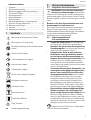
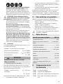
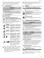
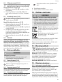
1 Symbole
Warnung vor allgemeiner Gefahr
Warnung vor Stromschlag
Betriebsanleitung, Sicherheitshinweise
lesen!
Gehörschutz tragen!
Schutzhandschuhe tragen!
Atemschutz tragen!
Schutzbrille tragen!
Nicht in den Hausmüll geben.
Akkupack einsetzen
Akkupack lösen
Hammerbohren
Schrauben/Bohren
Tipp, Hinweis
Handlungsanweisung
2 Sicherheitshinweise
2.1 Allgemeine Sicherheitshinweise
WARNUNG! Lesen Sie alle Sicherheits
hinweise und Anweisungen.
Versäumnis
se bei der Einhaltung der Sicherheitshinweise
und Anweisungen können elektrischen Schlag,
Brand und/oder schwere Verletzungen verursa
chen.
Bewahren Sie alle Sicherheitshinweise und
Anweisungen für die Zukunft auf.
Der in den Sicherheitshinweisen verwendete
Begriff „Elektrowerkzeug“ bezieht sich auf
netzbetriebene Elektrowerkzeuge (mit Netzlei
tung) und auf akkubetriebene Elektro
werkzeuge (ohne Netzleitung).
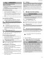
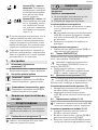
2.2 Maschinenspezifische
Sicherheitshinweise
– Tragen Sie Gehörschutz. Die Einwirkung
von Lärm kann Gehörverlust bewirken.
– Benutzen Sie die mit dem Gerät gelieferte
Zusatzhandgriffe.
Der Verlust der Kontrol
le kann zu Verletzungen führen.
– Halten Sie das Gerät an den isolierten
Griffflächen, wenn Sie Arbeiten ausfüh
ren, bei denen das Einsatzwerkzeug ver
borgene Stromleitungen treffen kann. Der
Kontakt mit einer spannungsführenden
Leitung kann auch metallene Geräteteile
unter Spannung setzen und zu einem elekt
rischen Schlag führen.
– Verwenden Sie geeignete Suchgeräte, um
verborgene Versorgungsleitungen aufzu
spüren, oder ziehen Sie die örtliche Ver
sorgungsgesellschaft hinzu. Der Kontakt
des Einsatzwerkzeuges mit einer span
nungsführenden Leitung kann zu Feuer
und einem elektrischem Schlag führen.
Beschädigung einer Gasleitung kann zur
Explosion führen. Eindringen in eine Was
serleitung verursacht Sachbeschädigung.
– Beim Arbeiten können schädliche/giftige
Stäube entstehen (z.B. bleihaltiger An
strich, einige Holzarten oder Metalle). Das
Berühren oder Einatmen dieser Stäube
kann für die Bedienperson oder in der Nä
he befindliche Personen eine Gefährdung
darstellen. Beachten Sie die in Ihrem Land
gültigen Sicherheitsvorschriften.
Tragen Sie zum Schutz Ihrer Gesundheit
eine P2-Atemschutzmaske.
Deutsch
7

–
Tragen Sie geeignete persönliche Schutz
ausrüstungen: Gehörschutz, Schutzbrille,
Staubmaske bei stauberzeugenden Arbei
ten, Schutzhandschuhe beim Bearbeiten
rauer Materialien und beim Werkzeug
wechsel.
VORSICHT! Elektrowerkzeug kann blo
ckieren und plötzlichen Rückschlag ver
ursachen! Sofort ausschalten!
– Ein im Material festsitzendes Werkzeug
kann durch Ändern der Drehrichtung ein
fach wieder herausgezogen werden.
– Verwenden Sie das Elektrowerkzeug nicht
im Regen oder in feuchter Umgebung.
Feuchtigkeit im Elektrowerkzeug kann zu
Kurzschluss und Brand führen.
– Ein-/Ausschalter nicht dauerhaft arretie
ren!
– Keine Netzteile oder Fremd-Akkupacks
zum Betreiben des Akku-Elektro
werkzeugs verwenden. Keine Fremd-La
degeräte zum Laden der Akkupacks ver
wenden. Die Verwendung von nicht vom
Hersteller vorgesehenem Zubehör kann zu
einem elektrischen Schlag und/oder
schweren Unfällen führen.
2.3 Emissionswerte
Die nach
EN 60745 ermittelten Werte betragen
typischerweise:
Hammerbohren in Beton
Schalldruckpegel L
PA
=
90 dB(A)
Schallleistungspegel L
WA
= 101 dB(A)
Unsicherheit K =
3 dB
VORSICHT
Beim Arbeiten eintretender Schall
Schädigung des Gehörs
► Gehörschutz benutzen.
Schwingungsemissionswert a
h
(Vektorsumme
dreier Richtungen) und Unsicherheit K ermittelt
entsprechend EN 60745:
Hammerbohren in Beton
a
h
=
14,2 m/s
2
K = 1,5 m/s
2
Die angegebenen Emissionswerte (Vibration,
Geräusch)
– dienen dem Maschinenvergleich,
– eignen sich auch für eine vorläufige Ein
schätzung der Vibrations- und Geräuschbe
lastung beim Einsatz,
– repräsentieren die hauptsächlichen An
wendungen des Elektrowerkzeugs.
Erhöhung möglich bei anderen Anwendungen,
mit anderen Einsatzwerkzeugen oder wenn un
genügend gewartet. Leerlauf- und Stillstands
zeiten der Maschine beachten!
3 Bestimmungsgemäße
Verwendung
Akku-Bohrhammer geeignet
– zum Hammerbohren in Beton, Ziegel und
Gestein,
– zum Bohren ohne Schlag in Holz, Metall,
Keramik und Kunststoff,
– zum Ein- und Festschrauben von Schrau
ben.
– für die Verwendung mit den Festool Akku
packs der Baureihe BP gleicher Span
nungsklasse.
Bei nicht bestimmungsgemäßem Ge
brauch haftet der Benutzer.
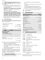
4 Technische Daten
Akku-Bohrhammer BHC 18
Motorspannung 18 V
Leerlaufdrehzahl
0 - 1100 min
-1
Schlagenergie 1,8 J
Spannhals 43 mm
Werkzeugaufnahme SDS-plus
Bohrdurchmesser max.:
Stahl 10 mm
Holz 25 mm
Hammerbohren in Be
ton
18 mm
Gewicht mit Zusatzhandgriff
ohne Akkupack
1,9 kg
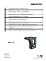
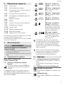
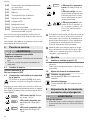
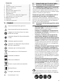
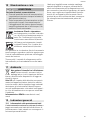
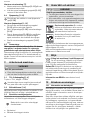
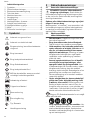
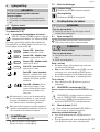
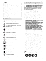
5 Geräteelemente
[1-1]
Werkzeugaufnahme
[1-2]
Entriegelungshülse
[1-3]
Schalter für Rechts-/Links-Lauf
[1-4]
Ein-/Ausschalter
Deutsch
8

[1-5]
Umschalter Bohren/Hammerbohren
[1-6]
Gürtelclip
[1-7]
Akkupack
[1-8]
Taste zum Lösen des Akkupacks
[1-9]
Kapazitätsanzeige
[1-10]
LED-Lampe
[1-11]
Zusatzhandgriff
[1-12]
Tiefenanschlag
[1-13]
Isolierte Griffflächen (grau schattier
ter Bereich)
Abgebildetes oder beschriebenes Zubehör ge
hört teilweise nicht in den Lieferumfang.
Die angegebenen Abbildungen befinden sich
am Anfang der Betriebsanleitung.
6 Inbetriebnahme
WARNUNG
Unzulässige Spannung oder Frequenz!
Unfallgefahr
► Angaben auf Typenschild beachten.
► Länderbesonderheiten beachten.
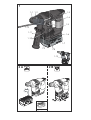
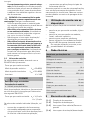
6.1 Akkupack wechseln
Akkupack einsetzen [2 A]
Akkupack abnehmen [2 B]
6.2 Beleuchtung und Akku-
Kapazitätsanzeige
Die LED der Lampe [1-10] dient als Be
leuchtung und als Akku-Kapazitätsanzei
ge [1-9].
Sie zeigt automatisch bei Betätigung des Ein-/
Ausschalters [1-4] den Ladezustand des Akku
packs an (nicht mit NiCd- und NiMH-Akku
packs).
LED grün – Dauerlicht: la
dezustand > 60 %
LED grün – langsames
blinken: Ladezustand
30 % – 60 %
LED grün – schnelles blin
ken:
Ladezustand 0 % -
30 %
LED gelb – Dauerlicht: ak
ku ist leer
LED rot – Dauerlicht: ak
ku-, Elektronik- oder Mo
tortemperatur ist außer
halb der zulässigen Grenz
werte.
LED rot – blinken: Allge
meine Fehleranzeige, z. B.
keine vollständige Kontak
tierung, Kurzschluss, Ak
kupack defekt, usw.
Wenn der Akkupack leer ist, bei Strom
ausfall oder wenn der Netzstecker gezo
gen wird, den Ein-/Ausschalter sofort in
die Aus-Position bringen. Dies verhindert
einen unkontrollierten Wiederanlauf.
Weitere Infos zu Ladegerät und Akkupack
mit Kapazitätsanzeige finden Sie in den
Betriebsanleitungen von Ladegerät und
Akkupack.
7 Einstellungen
7.1 Drehrichtung ändern [1-3]
– Schalter nach links = Rechtslauf
– Schalter nach rechts = Linkslauf
7.2 Betriebsart einstellen
Hammerbohren
Umschalter
[1-5] auf Hammersymbol.
Schrauben/Bohren
Umschalter
[1-5] auf Bohrsymbol.
8 Werkzeugaufnahme,
Vorsatzgeräte
WARNUNG
Verletzungsgefahr
► Vor allen Arbeiten am Elektrowerkzeug
den Akkupack vom Elektrowerkzeug ab
nehmen.
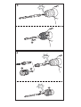
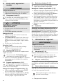
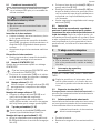
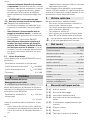
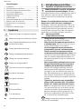
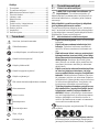
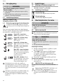
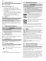
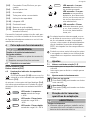
8.1 Werkzeug wechseln
[3]
Bohrwerkzeuge werden mit dem System
SDS-plus ohne Verwendung von Werk
zeugschlüsseln gespannt.
Deutsch
9

VORSICHT
Heißes und scharfes Werkzeug
Verletzungsgefahr
► Keine stumpfen und defekten Einsatzwerk
zeuge verwenden!
► Schutzhandschuhe tragen.
Werkzeug einsetzen
► Werkzeugschaft reinigen und mit Mehr
zweckfett bestreichen.
► Entriegelungshülse [1-2] nicht
zurückzie
hen, sondern Werkzeug drehend in Werk
zeugaufnahme [1-1] einführen bis es ein
rastet.
► Werkzeug auf festen Sitz prüfen.
Werkzeug entnehmen
► Entriegelungshülse [1-2] nach hinten
schieben und Werkzeug herausziehen.
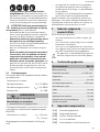
8.2 CENTROTEC Werkzeugfutter
[4]
Schneller Wechsel von Werkzeugen mit CENT
ROTEC-Schaft
CENTROTEC-Werkzeuge nur in CENT
ROTREC-Werkzeugfutter einspannen.
► Umschalter [1-5]
vor Arbeiten mit CENT
ROTEC-Werkzeugfutter auf Bohrsymbol
stellen.
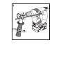
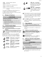
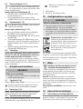
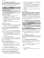
8.3 Zusatzhandgriff
[1-11]
Immer Zusatzhandgriff [1-11] verwenden
um eine sichere und ermüdungsarme Ar
beitshaltung zu gewährleisten.
Zusatzhandgriff montieren
[7]
► Zusatzhandgriff [1-11]
am Hals des Getrie
begehäuses aufsetzen.
► Griffstück des Zusatzhandgriffs [1-11] ge
gen Uhrzeigersinn drehen bis dieser fest
sitzt.
8.4 Tiefenanschlag
[1-12]
Mit dem Tiefenanschlag [1-12] kann die
Bohrtiefe eingestellt werden.
Tiefenanschlag [1-12] montieren
► Griffstück des Zusatzhandgriffs [1-11]
durch Drehen im Uhrzeigersinn aufdrehen.
► Tiefenanschlag [1-12] in Zusatzhand
griff [1-11] einsetzen.
► Tiefenanschlag [1-12] so weit herauszie
hen, dass Abstand zwischen Bohrerspitze
und Spitze von Tiefenanschlag gewünschter
Bohrtiefe entspricht.
► Griffstück des Zusatzhandgriffs [1-11]
wie
der festziehen.
8.5 Absaugen
Beachten Sie die in Ihrem Land gültigen Si
cherheitsvorschriften für Stäube. Am Arbeits
platz müssen die relevanten Grenzwerte ein
gehalten werden. Bei entsprechender Staub
belastung und je nach Vorschriften ist ggf. eine
Absaugung erforderlich. Dafür bietet Festool
eine Bohrstaubdüse im Zubehör-System an.
9 Arbeiten mit der Maschine
WARNUNG
Verletzungsgefahr
► Werkstück so befestigen, dass es sich beim
Bearbeiten nicht bewegen kann.
9.1 Ein-/Ausschalten [1-4]
Drücken = EIN, Loslassen = AUS
Je nach Druck auf den Ein-/Ausschalter ist
die Drehzahl stufenlos steuerbar.
9.2 Gürtelclip [1-6]
Der Gürtelclip (rechts/links) ermöglicht ein
kurzfristiges Befestigen des Gerätes an der Ar
beitskleidung.
9.3 Akustische Warnsignale
Akustische Warnsignale ertönen bei folgenden
Betriebszuständen und das Elektrowerkzeug
schaltet ab:
peep
Akku leer oder Elektrowerkzeug über
lastet:
► Akku wechseln
► Elektrowerkzeug weniger belasten
10 Wartung und Pflege
WARNUNG
Verletzungsgefahr, Stromschlag
► Vor allen Wartungs- und Pflegearbeiten
stets den Akkupack von dem Elektro
werkzeug abnehmen.
► Alle Wartungs- und Reparaturarbeiten, die
ein Öffnen des Motorgehäuses erfordern,
dürfen nur von einer autorisierten Kunden
dienstwerkstatt durchgeführt werden.
Kundendienst und Reparatur nur
durch Hersteller oder durch Ser
vicewerkstätten. Nächstgelegene
Adresse unter: www.festool.de/
service
Deutsch
10

Nur original Festool Ersatzteile ver
wenden! Bestell-Nr. unter:
www.festool.de/service
EKAT
1
2
3
5
4
Zur Sicherung der Luftzirkulation müssen die
Kühlluftöffnungen im Motorgehäuse stets frei
und sauber gehalten werden.
Die Anschlusskontakte am Elektrowerkzeug,
Ladegerät und Akkupack sauber halten.
11 Umwelt
Gerät nicht in den Hausmüll werfen!
Geräte, Zubehör und Verpackungen ei
ner umweltgerechten Wiederverwertung
zuführen. Geltende nationale Vorschriften be
achten.
Nur EU:
Gemäß Europäischer Richtlinie über
Elektro- und Elektronik-Altgeräte und Umset
zung in nationales Recht, müssen verbrauchte
Elektrowerkzeuge getrennt gesammelt und ei
ner umweltgerechten Wiederverwertung zuge
führt werden.
Informationen zur REACh: www.festool.com/
reach
12 Allgemeine Hinweise
12.1 Informationen zum Datenschutz
Das Elektrowerkzeug enthält einen Chip zur
automatischen Speicherung von Maschinen-
und Betriebsdaten. Die gespeicherten Daten
enthalten keinen direkten Personenbezug.
Die Daten können mit speziellen Geräten kon
taktlos ausgelesen werden, und werden von
Festool ausschließlich zur Fehlerdiagnose, Re
paratur- und Garantieabwicklung sowie zur
Qualitätsverbesserung bzw. Weiterentwicklung
des Elektrowerkzeugs verwendet. Eine darüber
hinausgehende Nutzung der Daten – ohne aus
drückliche Einwilligung des Kunden – erfolgt
nicht.
Deutsch
11

Contents
1 Symbols.....................................................12
2 Safety warnings.........................................12
3 Intended use
..............................................13
4 Technical data........................................... 13
5 Parts of the device.....................................13
6 Commissioning..........................................14
7 Settings......................................................14
8 Tool holder, attachments..........................14
9 Working with the machine........................ 15
10 Service and maintenance..........................15
11 Environment..............................................15
12 General information..................................16
1 Symbols
Warning of general danger
Warning of electric shock
Read the operating instructions and
safety instructions.
Wear ear protection.
Wear protective gloves.
Wear a dust mask.
Wear protective goggles.
Do not dispose of it with domestic
waste.
Inserting the battery pack
Removing the battery pack
Hammer drilling
Screwdriving/drilling
Tip or advice
Handling instruction
2 Safety warnings
2.1 General Power Tool Safety Warnings
WARNING! Read all safety warnings and
all instructions. Failure to follow the
warnings and instructions may result in electric
shock, fire and/or serious injury.
Safe all warnings and instructions for future
reference.
The term "power tool" in the warnings refers to
your mains-powered (corded) power tools or
battery-operated (cordless) power tools.
2.2 Machine-specific safety notices
– Wear ear protectors. Exposure to noise
can cause hearing loss.
– Use auxiliary handle(s), if supplied with
the tool.
Loss of control can cause person
al injury.
– Hold power tool by insulated gripping sur
faces, when performing an operation
where the cutting accessory may contact
hidden wiring.
Cutting accessory contact
ing a "live" wire may make exposed metal
parts of the power tool "live" and could give
the operator an electric shock.
– Use appropriate detection devices to look
for any hidden supply lines or consult your
local utility company. If the insertion tool
makes contact with live cables, it can result
in fire and electric shock. Damage to a gas
pipe can lead to an explosion. Penetration
of a water pipe can result in damage to
property.
– Harmful/toxic dust may be produced dur
ing your work (e.g. paint containing lead,
certain types of wood and metal).
Inhaling
or coming into contact with this dust may
represent a hazard for operating personnel
or persons in the vicinity. Comply with the
safety regulations that apply in your coun
try.
Wear a P2 dust mask to protect your
health.
–
Wear suitable personal protective equip
ment:
Ear protection, protective goggles,
dust mask for work that generates dust,
protective gloves for working with rough
materials and for changing tools.
English
12

CAUTION! Power tool can jam and cause
sudden kickback! Switch off immediately!
– If a tool becomes stuck in the material, it
can be removed simply by reversing the ro
tational direction of the machine.
– Do not use the power tool in the rain or in
damp surroundings. Moisture in the power
tool may cause a short circuit and fire.
– Do not lock the on/off switch in place per
manently.
– Do not use power supply units or third-
party battery packs to operate cordless
power tools. Do not use third-party charg
ers to charge the battery packs. The use of
accessories not expressly authorised by the
manufacturer can result in electric shocks
and/or serious accidents.
2.3 Emission levels
The levels determined in accordance with
EN 60745
are typically:
Hammer drilling in concrete
Sound pressure level L
PA
=
90 dB(A)
Sound power level L
WA
= 101 dB(A)
Uncertainty K = 3 dB
CAUTION
Noise generated when working
Risk of damage to hearing
► Use ear protection.
Vibration emission level a
h
(vector sum for
three directions) and uncertainty K measured in
accordance with EN 60745:
Hammer drilling in concrete
a
h
=
14.2 m/s
2
K=1.5 m/s
2
The specified emission levels (vibration, noise)
– are used to compare machines.
– They are also used for making preliminary
estimates regarding vibration and noise
load during operation.
– They represent the primary applications of
the power tool.
An increase is possible in other applications,
with other insertion tools or if the machine is
not maintained adequately. Take note of the
machine's idling and downtimes.
3 Intended use
Cordless rotary hammer suitable
– for hammer drilling in concrete, brick and
stone,
– for drilling in wood, metal, ceramic and
plastic with no impact function,
– for inserting and tightening screws.
– intended for use with BP Festool battery
packs of the same voltage class.
The user is liable for improper or non-in
tended use.
4 Technical data
Cordless hammer drill BHC 18
Motor voltage 18 V
Idle engine speed
0–1100 rpm
Impact energy 1.8 J
Flange 43 mm
Tool holder SDS-plus
Max. drill diameter:
Steel 10 mm
Wood 25 mm
Hammer drilling in
concrete
18 mm
Weight incl. additional handle,
excl. battery pack
1.9 kg
5 Parts of the device
[1-1]
Tool adapter
[1-2]
Release sleeve
[1-3]
Right/left switch
[1-4]
On/Off switch
[1-5]
Drilling/hammer drilling selector
switch
[1-6]
Belt clip
[1-7]
Battery pack
[1-8]
Button for releasing the battery pack
[1-9]
Capacity display
[1-10]
LED lamp
[1-11]
Auxiliary handle
[1-12]
Depth stop
[1-13]
Insulated gripping surfaces (grey
shaded area)
English
13

Accessories shown or described are not always
included in the scope of delivery.
The specified illustrations appear at the begin
ning of the Operating Instructions.
6 Commissioning
WARNING
Unauthorised voltage or frequency.
Risk of accidents
► Observe the specifications on the ma
chine's name plate.
► Observe country-specific regulations.
6.1 Changing the battery pack
Inserting the battery pack [2 A]
Removing the battery pack
[2 B]
6.2 Lighting and battery capacity indicator
The LED [1-10] provides light and acts as
a battery capacity indicator [1-9].
When the on/off switch
[1-4] is pressed, the
LED automatically displays the state of charge
of the battery pack (not for NiCd and NiMH bat
tery packs).
Green LED – steady light:
State of charge > 60%
Green LED – flashing
slowly: State of charge
30%–60%
Green LED – flashing
quickly: State of charge
0%–30%
Yellow LED – steady light:
Battery is flat
Red LED – steady light:
Temperature of the bat
tery, electronics or motor
is outside the permitted
range.
Red LED – flashing:
Gen
eral fault indicator, e.g. not
in full contact, short cir
cuit, faulty battery pack,
etc.
When the battery pack is empty, or if there
is a power failure or the mains plug is re
moved, move the on/off switch immediate
ly to the Off position. This prevents uncon
trolled restarting.
Further information about the charger and
battery pack with capacity indicator can be
found in the corresponding operating
manual.
7 Settings
7.1 Changing direction of rotation [1-3]
– Switch to the left = clockwise rotation
– Switch to the right = counterclockwise rota
tion
7.2 Selecting the operating mode
Hammer drilling
Set selector switch [1-5]
to hammer
symbol.
Screwdriving/drilling
Set selector switch [1-5] to drill symbol.
8 Tool holder, attachments
WARNING
Risk of injury
► Remove the battery pack from the power
tool before performing any work on the
power tool.
8.1 Changing tools [3]
Drills are clamped by means of the SDS-
plus system without using a wrench.
CAUTION
Hot and sharp tools
Risk of injury
► Do not use any blunt or defective insert
tools.
► Wear protective gloves.
Inserting the tool
► Clean the tool shank and apply a coating of
multipurpose grease.
► Do [1-2] not retract the release sleeve, but
insert the tool in the tool holder [1-1]
and
turn until it engages.
► Check that the tool is seated correctly.
Removing the tool
► Push the unlocking sleeve [1-2] back and
remove the tool.
8.2 CENTROTEC tool chuck [4]
Quick change of tools with CENTROTEC shaft
Only clamp CENTROTEC tools in CEN
TROTEC tool chucks.
English
14

► Before working with the CENTROTEC tool
chuck, set the selector switch [1-5] to the
drill symbol.
8.3 Auxiliary handle [1-11]
Always use the additional handle [1-11] to
guarantee a safe, non-tiring working pos
ture.
Attaching the additional handle [7]
► Attach the additional handle [1-11]
to the
neck of the gear housing.
► Turn the grip anticlockwise until the addi
tional handle [1-11] is secured in position.
8.4 Depth stop
[1-12]
The drilling depth can be adjusted using
the depth stop
[1-12].
Attaching the depth stop [1-12]
► Unscrew the additional handle [1-11] by
turning the grip anticlockwise.
► Insert the depth stop [1-12]
in the addition
al handle [1-11].
► Pull out the depth stop [1-12] until the dis
tance between the tip of the drill and the tip
of the depth stop corresponds to the desired
drilling depth.
► Tighten the grip on the additional handle
[1-11] again.
8.5 Extraction
Please observe the safety regulations applica
ble in your country for dust. The relevant limit
values must be observed at the workstation. A
dust extractor may be required for correspond
ing dust exposure and depending on regula
tions. Festool offers a drilling dust nozzle in the
accessories system.
9 Working with the machine
WARNING
Risk of injury
► Always secure the workpiece in such a
manner that it cannot move while being
machined.
9.1 On/Off switch [1-4]
Press = ON, release = OFF
The speed of the machine depends on how
far the on/off switch is pressed in.
9.2 Belt clip
[1-6]
The belt clip (right/left) allows the tool to be at
tached to work attire for brief periods.
9.3 Acoustic warning signal
Acoustic warning signals sound and the power
tool switches off in the following operating
states:
peep
Battery flat or power tool overloaded:
► Change the battery
► Reducing the load on the power tool
10 Service and maintenance
WARNING
Risk of injury, electric shock
► Always remove the battery pack from the
power tool before performing any mainte
nance or service work.
► All maintenance and repair work which re
quires the motor housing to be opened
should always be carried out by an author
ised service workshop.
Customer service and repairs
must
only be carried out by the manufac
turer or service workshops. Find the
nearest address at:
www.festool.co.uk/service
Always use original Festool spare
parts. Order no. at:
www.festool.co.uk/service
EKAT
1
2
3
5
4
To ensure constant air circulation, always keep
the cooling air openings in the motor housing
clean and free of blockages.
Keep the contacts on the power tool, charger
and battery pack clean.
11 Environment
Do not dispose of the device in the
household waste! Recycle devices, ac
cessories and packaging. Observe appli
cable national regulations.
EU only: In accordance with the European Di
rective on waste electrical and electronic
equipment and implementation in national law,
used power tools must be collected separately
and handed in for environmentally friendly re
cycling.
Information on REACH: www.festool.com/reach
English
15

12 General information
Imported into the UK by
Festool UK Ltd
1 Anglo Saxon Way
Bury St Edmunds
IP30 9XH
Great Britain
12.1 Information on data privacy
The power tool contains a chip which automati
cally stores machine and operating data. The
data saved cannot be traced back directly to an
individual.
The data can be read in a contactless manner
using special devices and shall only be used by
Festool for fault diagnosis, repair and warranty
processing and for quality improvement or en
hancement of the power tool. The data shall not
be used in any other way without the express
consent of the customer.
English
16

Sommaire
1 Symboles...................................................17
2 Consignes de sécurité
...............................17
3 Utilisation conforme..................................18
4 Caractéristiques techniques.....................18
5 Éléments de l'appareil..............................19
6 Mise en service..........................................19
7 Réglages....................................................19
8 Porte-outil, appareils à monter................20
9 Utilisation de l'appareil.............................20
10 Entretien et maintenance......................... 21
11 Environnement..........................................21
12 Remarques générales...............................21
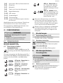
1 Symboles
Avertit d'un danger général
Avertit d'un risque de décharge électri
que
Lire le mode d'emploi et les consignes
de sécurité !
Porter une protection auditive !
Porter des gants de protection !
Porter une protection respiratoire !
Porter des lunettes de protection !
Ne pas jeter avec les ordures ménagè
res.
Insérer la batterie
Dégager la batterie
Perçage avec percussion
Vissage/perçage
Conseil, information
Instruction
2 Consignes de sécurité
2.1 Consignes générales de sécurité
AVERTISSEMENT ! Veuillez lire toutes
les consignes de sécurité et instructions.
Le non-respect des consignes de sécurité et
des instructions peut provoquer une décharge
électrique, un incendie et/ou des blessures
graves.
Conserver toutes les consignes de sécurité et
instructions afin de pouvoir les consulter ulté
rieurement.
Le terme « outil électroportatif » utilisé dans
les consignes de sécurité se rapporte aux outils
électroportatifs fonctionnant sur secteur (avec
câble) et aux outils électroportatifs fonction
nant sur batterie (sans câble).
2.2 Consignes de sécurité spécifiques à
l'appareil
– Portez une protection auditive !
L'effet du
bruit peut occasionner des pertes auditives.
– Utilisez les poignées supplémentaires
fournies avec l'appareil. Une perte de con
trôle peut provoquer des blessures.
– Si l'outil monté pourrait entrer en contact
avec des lignes électriques invisibles, te
nez l'appareil à l'aide des poignées iso
lées. Le contact avec un câble sous tension
peut également mettre des pièces métalli
ques de l'appareil sous tension et provo
quer une décharge électrique.
– Utilisez des appareils de détection appro
priés pour repérer les câbles d'alimenta
tion invisibles ou consultez l'entreprise de
distribution locale. Le contact de l'outil
monté avec un câble sous tension peut pro
voquer un feu ou une décharge électrique.
Une conduite de gaz endommagée peut
provoquer une explosion. Le perçage dans
une conduite d'eau provoque des dégâts
matériels.
– Au cours du travail, des poussières noci
ves/toxiques peuvent être générées (com
me les poussières de peintures au plomb
et certaines poussières de bois ou de mé
taux). Le contact ou l'inhalation de ces
poussières peut présenter un danger pour
la santé de l'utilisateur ou des personnes
se trouvant à proximité. Veuillez respecter
les prescriptions de sécurité en vigueur
dans votre pays.
Pour votre santé, portez un masque de
protection respiratoire de classe P2.
Français
17

–
Portez un équipement de protection indi
viduelle approprié :
une protection auditi
ve, des lunettes de protection, un masque
anti-poussière lors des travaux impliquant
un dégagement de poussière et des gants
de protection dans le cas des matériaux ru
gueux et lors du changement d'outil.
ATTENTION ! L'outil électroportatif peut
se bloquer et provoquer un rebond brus
que ! Mettre à l'arrêt immédiatement !
– Si un outil est coincé dans le matériau, il
est possible de le sortir facilement en
changeant de sens de rotation.
– Ne pas utiliser l'outil électroportatif sous
la pluie ou dans un environnement humi
de. L'humidité dans l'outil électroportatif
peut causer un court-circuit et provoquer
un incendie.
– Ne pas bloquer constamment l'interrup
teur marche/arrêt !
– Ne pas faire fonctionner l'outil électropor
tatif sans fil avec des blocs d'alimentation
secteur ou avec des batteries d'autres fa
bricants. Ne pas utiliser de chargeurs
d'autres fabricants pour recharger la bat
terie.
L'utilisation d'accessoires autres que
ceux prévus par le fabricant peut provoquer
une décharge électrique et/ou des acci
dents graves.
2.3 Valeurs d'émission
Les valeurs typiques déterminées selon
EN 60745
sont les suivantes :
Perçage avec percussion dans le béton
Niveau de pression acousti
que
L
PA
=
90 dB(A)
Niveau de puissance acous
tique
L
WA
= 101 dB(A)
Incertitude K = 3 dB
ATTENTION
Émission de bruit lors de l'utilisation
Lésions auditives
► Utiliser une protection auditive.
Valeur d'émission vibratoire a
h
(somme vecto
rielle tridirectionnelle) et incertitude K détermi
nées conformément à EN 60745 :
Perçage avec percussion dans
le béton
a
h
=
14,2 m/s
2
K = 1,5 m/s
2
Les valeurs d'émission indiquées (vibrations,
bruit)
– sont fournies à des fins de comparaison
avec d'autres appareils,
– permettent également une estimation pro
visoire de l'exposition aux vibrations et au
bruit lors de l'utilisation,
– sont représentatives des principales appli
cations de l'outil électroportatif.
Les émissions sonores peuvent être plus éle
vées pour d'autres applications, avec d'autres
outils montés ou en cas d'entretien insuffisant.
Tenir compte des temps de marche à vide et
d'immobilisation de l'appareil !
3 Utilisation conforme
Convient pour les perforateurs sans fil
– pour percer avec percussion dans le béton,
la brique et la pierre,
– pour percer sans percussion dans le bois,
le métal, la céramique et le plastique,
– pour visser et serrer des vis.
– pour l'utilisation avec les batteries Festool
de la série BP de catégorie de tension iden
tique.
L'utilisateur est responsable des dom
mages provoqués par une utilisation non
conforme.
4 Caractéristiques techniques
Perforateur sans fil BHC 18
Tension du moteur 18 V
Vitesse de rotation à
vide
0-1100 min
-1
Énergie de choc 1,8 J
Collet 43 mm
Porte-outil SDS-plus
Diamètre de perçage max. :
Acier 10 mm
Bois 25 mm
Perforation dans le bé
ton
18 mm
Poids avec poignée supplé
mentaire sans batterie
1,9 kg
Français
18

5 Éléments de l'appareil
[1-1]
Porte-outils
[1-2]
Douille de déverrouillage
[1-3]
Commutateur pour rotation à droite /
rotation à gauche
[1-4]
Interrupteur de marche/arrêt
[1-5]
Commutateur perçage/perçage avec
percussion
[1-6]
Clip pour ceinture
[1-7]
Batterie
[1-8]
Touche d'extraction du bloc batterie
[1-9]
Affichage de la capacité
[1-10]
Lampe à LED
[1-11]
Poignée supplémentaire
[1-12]
Butée de profondeur
[1-13]
Poignée isolée (zone grisée)
Les accessoires illustrés ou décrits ne font pas
tous partie des éléments livrés.
Les illustrations indiquées se trouvent en début
de notice d'utilisation.
6 Mise en service
AVERTISSEMENT
Tension ou fréquence non admissible !
Risque d'accident
► Tenir compte des indications fournies sur
la plaque signalétique.
► Tenir compte des particularités propres au
pays.
6.1 Remplacement de la batterie
Insertion de la batterie [2 A]
Retirer la batterie
[2 B]
6.2 Éclairage et témoin de charge de
batterie
Le témoin LED de la lampe [1-10] sert
d'éclairage et de témoin de charge de
batterie [1-9]
.
À l'actionnement de l'interrupteur marche/
arrêt
[1-4], il indique automatiquement le ni
veau de charge de la batterie (sauf avec les bat
teries NiCd et NiMH).
LED verte – allumée en
continu : niveau de charge
> 60 %
LED verte – clignotement
lent : niveau de charge
30 % – 60 %
LED verte – clignotement
rapide :
niveau de charge
0 % - 30 %
LED jaune – allumée en
continu : la batterie est vi
de
LED rouge – allumée en
continu : la température
de la batterie, du système
électronique ou du moteur
se site hors des limites de
tolérance admissibles.
LED rouge – clignote
ment : défaut général, par
ex. pas de contact total,
court-circuit, batterie dé
fectueuse, etc.
Si la batterie est vide, qu'une panne de
courant se produit ou que la prise secteur
est débranchée, mettre immédiatement
l'interrupteur marche/arrêt en position
d'arrêt. Ceci permet d'éviter tout redémar
rage intempestif.
Vous trouverez des informations supplé
mentaires sur le chargeur et la batterie à
indicateur de charge dans les notices
d'utilisation de ces deux éléments.
7 Réglages
7.1 Changement de sens de rotation [1-3]
– Commutateur vers la gauche = rotation à
droite
– Commutateur vers la droite = rotation à
gauche
7.2 Réglage du mode de fonctionnement
Perçage avec percussion
Commutateur [1-5] sur le symbole mar
teau.
Vissage/perçage
Commutateur [1-5]
sur le symbole per
çage.
Français
19

8 Porte-outil, appareils à
monter
AVERTISSEMENT
Risque de blessures
► Retirer la batterie de l'outil électroportatif
avant toute intervention sur ce dernier.
8.1 Changement d'outil [3]
Le serrage des outils de perçage s'effec
tue au moyen du système SDS-plus, sans
utiliser de clés à outils.
ATTENTION
Outil chaud et tranchant
Risque de blessures
► Ne pas monter d'outils émoussés ou dé
fectueux !
► Porter des gants de protection.
Montage de l'outil
► Nettoyer la tige de l'outil et l'enduire de
graisse polyvalente.
► [1-2]
Sans retirer la douille de déverrouil
lage, introduire l'outil dans le porte-outil
[1-1] en le tournant jusqu'à ce qu'il se blo
que.
► Vérifier que l'outil est bien fixé.
Retrait de l'outil
► Repousser la douille de déverrouillage
[1-2] en arrière et sortir l'outil.
8.2 Mandrin CENTROTEC
[4]
La tige CENTROTEC permet un remplacement
rapide des outils
Serrer les outils CENTROTEC unique
ment dans un mandrin CENTROTEC.
► Placer le commutateur [1-5] sur le symbole
de perçage avant l'utilisation du mandrin
CENTROTEC.
8.3 Poignée supplémentaire [1-11]
Utiliser toujours la poignée supplémen
taire [1-11]
pour garantir une position de
travail sûre et sans fatigue.
Montage de la poignée supplémentaire [7]
► Placer la poignée supplémentaire [1-11]
sur le col du carter d'engrenage.
► Tourner la poignée supplémentaire [1-11]
dans le sens inverse des aiguilles d'une
montre jusqu'à ce qu'elle soit fixée.
8.4 Butée de profondeur [1-12]
La butée de profondeur [1-12] permet de
régler la profondeur de perçage.
Montage de la butée de profondeur [1-12]
► Dévisser la poignée supplémentaire [1-11]
en la tournant dans le sens horaire.
► Placer la butée de profondeur [1-12] dans
la poignée supplémentaire [1-11]
.
► Sortir progressivement la butée de profon
deur [1-12] jusqu'à ce que l'écart entre la
pointe du foret et la pointe de la butée de
profondeur corresponde à la profondeur de
perçage souhaitée.
► Resserrer la poignée supplémentaire
[1-11] .
8.5 Aspiration
Respectez la réglementation de sécurité de
votre pays concernant les poussières. Les va
leurs limites doivent être respectées sur le
poste de travail.
Une aspiration est éventuelle
ment requise si la charge de poussières est
élevée et en fonction des prescriptions. Dans ce
cas, Festool propose une buse pour poussière
de perçage comme accessoire.
9 Utilisation de l'appareil
AVERTISSEMENT
Risques de blessures
► Fixer la pièce à usiner de manière à ce
qu‘elle ne puisse pas bouger pendant le
traitement.
9.1 Marche/arrêt
[1-4]
Presser = ON, relâcher = OFF
Selon la pression sur l'interrupteur de
marche/arrêt, la vitesse de rotation peut
être commandée progressivement.
9.2 Clip pour ceinture [1-6]
Le clip pour ceinture (à droite/gauche) permet
une fixation rapide de l'appareil au vêtement de
travail.
9.3 Signaux d'avertissement sonores
Des signaux d'avertissement sonores retentis
sent dans les états de fonctionnement suivants
et l'outil électroportatif s'arrête :
peep
Batterie déchargée ou outil électro
portatif en surcharge :
► Changement de batterie
Français
20
Strona się ładuje...
Strona się ładuje...
Strona się ładuje...
Strona się ładuje...
Strona się ładuje...
Strona się ładuje...
Strona się ładuje...
Strona się ładuje...
Strona się ładuje...
Strona się ładuje...
Strona się ładuje...
Strona się ładuje...
Strona się ładuje...
Strona się ładuje...
Strona się ładuje...
Strona się ładuje...
Strona się ładuje...
Strona się ładuje...
Strona się ładuje...
Strona się ładuje...
Strona się ładuje...
Strona się ładuje...
Strona się ładuje...
Strona się ładuje...
Strona się ładuje...
Strona się ładuje...
Strona się ładuje...
Strona się ładuje...
Strona się ładuje...
Strona się ładuje...
Strona się ładuje...
Strona się ładuje...
Strona się ładuje...
Strona się ładuje...
Strona się ładuje...
Strona się ładuje...
Strona się ładuje...
Strona się ładuje...
Strona się ładuje...
Strona się ładuje...
Strona się ładuje...
Strona się ładuje...
Strona się ładuje...
Strona się ładuje...
Strona się ładuje...
Strona się ładuje...
Strona się ładuje...
Strona się ładuje...
Strona się ładuje...
Strona się ładuje...
Strona się ładuje...
Strona się ładuje...
Strona się ładuje...
Strona się ładuje...
Strona się ładuje...
-
 1
1
-
 2
2
-
 3
3
-
 4
4
-
 5
5
-
 6
6
-
 7
7
-
 8
8
-
 9
9
-
 10
10
-
 11
11
-
 12
12
-
 13
13
-
 14
14
-
 15
15
-
 16
16
-
 17
17
-
 18
18
-
 19
19
-
 20
20
-
 21
21
-
 22
22
-
 23
23
-
 24
24
-
 25
25
-
 26
26
-
 27
27
-
 28
28
-
 29
29
-
 30
30
-
 31
31
-
 32
32
-
 33
33
-
 34
34
-
 35
35
-
 36
36
-
 37
37
-
 38
38
-
 39
39
-
 40
40
-
 41
41
-
 42
42
-
 43
43
-
 44
44
-
 45
45
-
 46
46
-
 47
47
-
 48
48
-
 49
49
-
 50
50
-
 51
51
-
 52
52
-
 53
53
-
 54
54
-
 55
55
-
 56
56
-
 57
57
-
 58
58
-
 59
59
-
 60
60
-
 61
61
-
 62
62
-
 63
63
-
 64
64
-
 65
65
-
 66
66
-
 67
67
-
 68
68
-
 69
69
-
 70
70
-
 71
71
-
 72
72
-
 73
73
-
 74
74
-
 75
75


Festool BHC 18 C 3,1 I-Plus Instrukcja obsługi
- Kategoria
- Młoty obrotowe
- Typ
- Instrukcja obsługi
- Niniejsza instrukcja jest również odpowiednia dla
w innych językach
Powiązane artykuły
-
Festool PDC 18/4 5,2/4,0 I-Plus-SCA Instrukcja obsługi
-
-
-
-
Festool TPC 18/4 5,2/4,0 I-Plus-SCA Instrukcja obsługi
-
-
-
Festool C 18 Li 3,1-Compact Instrukcja obsługi
-
-