ECOWITT WS80 Solar Powered Ultrasonic Anemometer Instrukcja obsługi
- Typ
- Instrukcja obsługi

1
Ultrasonic Anemometer with Light &
UV, Thermo-hygrometer Sensors
Model: WS80
Contents
1. Introduction ..................................................................2
2. Unpacking ....................................................................2
3. Overview ......................................................................5
4. Setup Guide ..................................................................6
4.1 Install batteries in sensor package ..................... 6
4.2 Mount ultrasonic anemometer assembly ...........7
5. Wi-Fi Configure with gateway .................................. 15
5.1 Pair with gateway or display console .............. 15
5.2 Wi-Fi Connection ............................................ 16
6. View Online Data on WS View Plus or Ecowitt App16
7. Specification .............................................................. 17
7.1 Wireless Specifications: ...................................17
7.2 Measurement Specification ............................. 18
7.3 Power consumption ......................................... 19
8. Warranty Information ................................................ 19
9. URL of This Manual ..................................................20

2
1. Introduction
Thanks for your purchasing this WS80 6-in-1
Ultrasonic Sensor Package. This device measures
wind speed, wind direction, temperature, humidity,
UV Index and solar radiation. The Ultrasonic Sensor
Package is solar powered and sends data to the
receiver via a low-power radio. The data can be
streamed by GW1100 Wi-Fi Gateway (sold separately)
or HP2551/HP2553 console display (sold separately);
and can be viewed on our WS View Plus or Ecowitt
App application after the Wi-Fi configuration done.
To ensure the best product performance, please read
this manual and retain it for future reference.
2. Unpacking
Open your weather station box and inspect that the
contents are intact (nothing broken) and complete
(nothing missing). Inside you should find the
following:

3
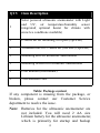
QTY
Item Description
1
Solar powered ultrasonic anemometer with Light
and UV, air temperature/humidity sensor
integrated( optional heater for climate with
snow/ice conditions available)
1
U-Bolts set for mounting on a pole (2pcs/set)
1
Threaded nuts for U-Bolts set (M6 size) (4pcs/set)
1
Mounting arm for ultrasonic anemometer
1
Mounting bracelet for ultrasonic anemometer
1
User manual (this manual)
1
3M extension cord
Table: Package content
If any component is missing from the package, or
broken, please contact our Customer Service
department to resolve the issue.
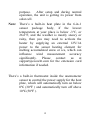
Note: Batteries for the ultrasonic anemometer are
not included. You will need 2 AA size
Lithium battery for the ultrasonic anemometer,
which is primarily for startup and backup

4
purpose. After setup and during normal
operation, the unit is getting its power from
solar cell.
Note: There’s a built-in heat plate in the 6-in-1
sensor package body, if the lowest
temperature at your place is below -3°C, or
26.6°F, and the weather is mostly snowy or
rainy, then you may need to activate the
heater by supplying an external 12V/1A
power to the sensor heating element for
melting accumulated snow or ice, which can
influence wind measurement accuracy
significantly. Please contact us at
[email protected]om for the extension cord
information if needed.
There’s a built-in thermostat inside the anemometer
sensor to control the power supply for the heat
plate, which will automatically turn on below
0℃(30℉) and automatically turn off above
10℃(50℉).

5
3. Overview
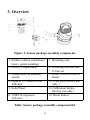
Figure 1: Sensor package assembly components
1. Surface tension conditioner
layer ( patent pending)
7. Mounting arm
2. Battery compartment
8. Mounting bracelet and
U-bolt set
3. Temperature & humidity
sensor
9. Power cord for built-in
heater
4. Light & UV sensor, LED
indicator
10. USB port (factory use
only )
5. Solar Panel
11.Calibration button
(factory use only )
6. NORTH alignment
indicator
12. Reset button
Table: Sensor package assembly component list

6
4. Setup Guide
4.1 Install batteries in sensor package
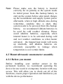
Open the battery compartment with a screwdriver and
insert 2 AA batteries in the battery compartment, and
press “Reset” button, the LED indicator on the back of
the sensor package (item 4) will turn on for 3 seconds
and then flash once every 4.8 seconds indicating
sensor data transmission. If you did not pay attention,
you may have missed the initial indication. You can
always press the reset button to start over. Make sure
you see the flash once every 4.8 seconds.
If sensor has been put outside for some time, and solar
panel has charged up the internal accumulator fully or
partially, if you install the 2 AA backup battery, the
system might not start up properly. So you can always
make a system reset by press the “Reset” button.
Figure 2: Battery installation diagram

7
Note: Please make sure the battery is inserted
correctly for its polarity as the system needs
its initial power from this backup battery to
start up the system before solar panel charges
up the accumulator and supply system power
afterwards. when in high altitude area, during
wintertime, sunshine time is short, thus
system needs to be powered from this backup
battery, we recommend Lithium batteries to
be used for cold weather climates. Please
avoid alkaline batteries, especially when
internal heater is to be activated during cold
and wet weather conditions as when heater
activated, the trapped heat inside will warm
up internally, and alkaline batteries are
extremely susceptible to leakage when
temperature is over certain limits.
4.2 Mount ultrasonic anemometer assembly
4.2.1 Before you mount
Before installing your outdoor sensor in the
permanent location, we recommend operating the
device for one week in a temporary location with easy
access. This will allow you to check out all of the
functions, ensure proper operation and familiarize you
with the device performance.

8
4.2.2 Mounting
You can attach a pole(not included) to a
permanent structure and then attach the sensor
package to it (see Figure 3-8).
The U-Bolts will accommodate a pole diameter of
1.25-2 inches (pole not included).
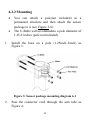
1. Install the base on a pole (1.25inch~2inch) as
Figure 3.
Figure 3: Sensor package mounting diagram 6-1
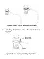
2. Pass the connector cord through the arm tube as
Figure 4:

9
Figure 4: Sensor package mounting diagram 6-2
3. Attaching the arm tube to the Ultrasonic Sensor as
Figure 5.
Figure 5: Sensor package mounting diagram 6-3

10
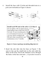
4. Install the base with U-bolts and threaded nuts to a
pole (not included) as Figure 6 shows:
Figure 6: Sensor package mounting diagram 6-4
5. Insert the arm tube into the base as Figure 7. Be
sure to line up the small hole in the arm with the
holes in the base. Insert the machine screw through
the holes in the base and arm. ( if you don’t need to

11
power up the heater, you should keep the power
cord terminal inside the mounting arm and this can
make the installation looks neat and tidy. You may
take it out when needed.)
Figure 7: Sensor package mounting diagram 6-5
Make sure the mounting pole is vertical, or very close
to it. Use a level as needed.
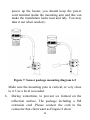
6. During wintertime, to prevent ice formed on the
reflection surface, The package including a 3M
extension cord ,Please connect the cord to the
connector that client want as Fingure 8 show

12
Figure 8: Sensor package mounting diagram 6-6
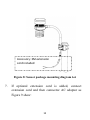
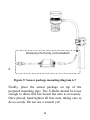
7. If optional extension cord is added, connect
extension cord and then connector AC adaptor as
Figure 9 show:
Accessory: 3M extension
cord included

13
8.
Figure 9: Sensor package mounting diagram 6-7
Finally, place the sensor package on top of the
prepared mounting pipe. The U-Bolts should be loose
enough to allow this but loosen the nuts as necessary.
Once placed, hand tighten all four nuts, taking care to
do so evenly. Do not use a wrench yet!
Accessory Part only, not included!

14
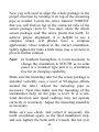
Now you will need to align the whole package in the
proper direction by rotating it on top of the mounting
pipe as needed. Locate the arrow labeled “NORTH”
that you will find on top of the connector tube of the
sensor package (item 6). You must rotate the whole
sensor package until this arrow points due north. To
achieve proper alignment, it is helpful to use a
compass (many cell phones have a compass
application). Once rotated in the correct orientation,
lightly tighten the bolts a little more (use a wrench) to
prevent further rotation.
Note: In Southern hemisphere, it is not necessary to
change the orientation to SOUTH as its solar
panel is a rounded type and it is orientation
free for its charging capability.
Make sure the mounting tube for the sensor package is
installed vertically (use a level at 90-degree offsets
around the tube). Adjust the mounting pipe as
necessary. Next also make sure the mounting of the
anemometer body on the pipe is level. If it is not,
wind direction and speed readings may not operate
correctly or accurately. Adjust the mounting assembly
as necessary.
Make sure you check, and correct if necessary, the
north orientation again, as the final installation step,
and now tighten the bolts with a wrench. Do not over

15
tighten, but make sure strong wind and/or rain cannot
move the sensor package.
4.2.3 Reset Button and Transmitter LED
In the event the sensor package is not transmitting,
reset the sensor.
Using a bent-open paperclip, press and hold the
RESET BUTTON (item 12) to affect a reset: the LED
turns on while the RESET button is depressed, and
you can now let go. The LED should then resume as
normal, flashing approximately once every 4.8
seconds.
5. Wi-Fi Configure with gateway
If you want to view the Ultrasonic Sensor data on
your mobile application, you need to pair this device
with our GW1100 Wi-Fi Gateway or HP2551/HP2553
display console (sold separately).
5.1 Pair with gateway or display console
Please follow the tips to pair your sensor(s) with the
Wi-Fi Gateway or HP2550/HP2551 display console:
1) Power on the gateway first (with USB connection)

16
or HP2551/HP2553 display console (with adaptor
connection)
2) Power on the Ultrasonic sensor.
3) The RF status indicator of the gateway will light on
steady, and light off once when it receives the data
from the optional sensor(s) once.
4) If work normally, you can forward to the Wi-Fi
connection operation.
5.2 Wi-Fi Connection
For this part, please refer to the manual of the
GW1100 Wi-Fi gateway or HP2551/HP2553 Wi-Fi
Weather Station.
Any question, please contact the customer service.
6. View Online Data on WS View Plus
or Ecowitt App
When the Wi-Fi configuration is done, you can view
the live data of your ultrasonic sensor on the WS
View Plus or Ecowitt App application(only for the
GW1100 gateway).

17
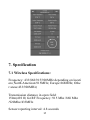
7. Specification
7.1 Wireless Specifications:
Frequency: 433/868/915/920MHz depending on locati
on (North American:915MHz; Europe:868MHz; Othe
r areas:433/920MHz)
Transmission distance in open field:
150m(492 ft) for RF Frequency :915 Mhz /868 Mhz
/920Mhz/433MHz
Sensor reporting interval: 4.8 seconds

18
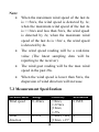
Note:
When the maximum wind speed of the last 4s
is >=5m/s, the wind speed is detected by 1s;
when the maximum wind speed of the last 4s
is >=3m/s and less than 5m/s, the wind speed
is detected by 2s; when the maximum wind
speed of the last 4s is <3m/ s, the wind speed
is detected by 4s.
The wind speed reading will be a real-time
value (The latest sampling data will be
reporting to the receiver).
The wind gust reading will be the max wind
speed in the past 28s.
When the wind speed is lower than 5m/s, the
dispersion of wind direction will increase.
7.2 Measurement Specification
Measurement
Range
Accuracy
Resolution
Wind speed
0~40m/s
<10m/s,
+/-0.5m/s
≥10m/s,
+/-5%
0.1M/S
Wind
direction
0~359°
<10m/s, TBA
≥10m/s, ±15°
1°

19
Temperature
-40~60℃
±1℃
0.1℃
Humidity
1~99%
±5%
1%
Light
0~300Klux
±15%
10Lux
UVI
1~15
±2
1
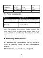
7.3 Power consumption
Power
Specification
Anemometer sensor
Solar panel (built-in): 6.5V/4mA
Anemometer sensor
(backup)
2 x AA 1.5V Lithium battery
(not included)
Note: The primary power source for the sensor is the
solar panel. When available solar power (light over
recent period) is insufficient, the batteries will be
used.
8. Warranty Information
We disclaim any responsibility for any technical
error or printing error, or the consequences
thereof.
All trademarks and patents are recognized.

20
We provide a 1-year limited warranty on this product
against manufacturing defects, or defects in materials
and workmanship.
This limited warranty begins on the original date of
purchase, is valid only on products purchased, and
only to the original purchaser of this product. To
receive warranty service, the purchaser must contact
us for problem determination and service procedures.
This limited warranty covers only actual defects
within the product itself and does not cover the cost of
installation or removal from a fixed installation,
normal set-up or adjustments, or claims based on
misrepresentation by the seller, or performance
variations resulting from installation-related
circumstances.
9. URL of This Manual
https://www.ecowitt.com/support/download/34
Please view this URL and you can download
the electronic archives of this manual.
Strona jest ładowana ...
-
 1
1
-
 2
2
-
 3
3
-
 4
4
-
 5
5
-
 6
6
-
 7
7
-
 8
8
-
 9
9
-
 10
10
-
 11
11
-
 12
12
-
 13
13
-
 14
14
-
 15
15
-
 16
16
-
 17
17
-
 18
18
-
 19
19
-
 20
20
-
 21
21


